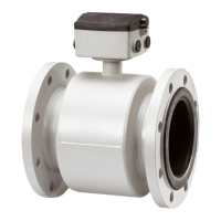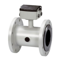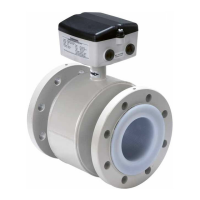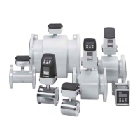
Do you have a question about the Siemens SITRANS F M MAG 5000 and is the answer not in the manual?
| Enclosure Rating | IP67, NEMA 4X |
|---|---|
| Ambient Temperature Range | -20 to +60 °C (-4 to +140 °F) |
| Type | Electromagnetic flow meter |
| Measurement Principle | Faraday's law of electromagnetic induction |
| Protection Class | IP67, NEMA 4X |
| Power Supply | 24 V DC, 100-240 V AC |
| Output | 4-20 mA, pulse, frequency |
| Communication | HART, PROFIBUS PA |
| Sizes | DN 15 to DN 2000 |
| Lining Material | PTFE, PFA |
| Electrode Material | Stainless steel, Hastelloy, Platinum, Tantalum |
| Process Temperature | Up to 180 °C (356 °F) depending on liner |
| Pressure Rating | Up to 40 bar (580 psi) depending on size and material |
| Approvals | ATEX, FM, CSA |
| Measuring Range | 0.01 to 12 m/s (0.03 to 40 ft/s) |
| Process Pressure | Max 40 bar (depending on size and lining) |
| Output Signals | 4-20 mA, pulse, frequency |
| Material | Carbon steel, Stainless steel |
| Installation | insertion |
Information for using the device, aimed at installation, connection, configuration, and maintenance personnel.
List of components included in the SITRANS F M MAG 5000/6000 transmitter package.
Special requirements and guidelines for installing equipment in hazardous environments.
Explains the electromagnetic induction principle used for flow measurement in the transmitters.
Details the suitable industries and applications for the magnetic flowmeters.
Specifies environmental and physical conditions required for optimal flow measurement installation.
Step-by-step guide for installing the compact version of the MAG 5000/6000 transmitter.
Instructions for performing a remote installation of the transmitter, covering sensor and wall mounting aspects.
Provides detailed wiring diagrams and instructions for connecting the transmitter's power supply and outputs.
Specific electrical connection details for PTB K7.2 approved MAG5000/6000 with MAG5100W.
Explanation of the transmitter's local user interface, including display fields and mode symbols.
Instructions on how to change the password to access and modify transmitter settings.
Guide to configuring fundamental parameters like flow direction, Qmax, units, and error levels.
Configuration options for current, digital, and relay outputs, including range, polarity, and error settings.
How to use external input signals for batch control, totalizer reset, or force/freeze output functions.
Instructions for resetting totalizers/counters or restoring the transmitter to its factory default settings.
Overview of the error system, acceptance levels, and how error information is displayed and logged.
A comprehensive table detailing error codes, their descriptions, causes, and recommended remedies.
A guide for troubleshooting unstable or incorrect measurements by checking the transmitter and its connections.
Detailed specifications for the MAG 5000/6000 transmitters, covering measurement principles, input/output, and operating conditions.
Provides flowmeter accuracy data and uncertainty curves for different flow velocities.
Details available spare parts for the transmitters, including connection plates, SENSORPROM units, and display units.
Provides a visual overview of the menu structure for MAG 5000/6000 and MAG 6000 I transmitters.
Diagram illustrating the menu flow for configuring basic settings, including units and customer-specific options.
Menu diagram for configuring the current output settings, including signal range and alarm behavior.
Menu diagram for setting up digital outputs for pulse functions, including volume, pulse width, and polarity.
Specific reset mode menu diagram for the MAG 6000 SV, including auto and manual zero adjustment.
Table detailing the default factory settings for various parameters of the MAG 5000/6000 transmitters.
Factory settings specific to 50 Hz operation and different pipe dimensions for MAG 1100, MAG 1100F, MAG 3100, MAG 3100 P, MAG 5100W.
Factory settings for 60 Hz operation across various pipe sizes for MAG 1100, MAG 1100F, MAG 3100, MAG 3100 P, MAG 5100W.


