INSTRUCTIONS
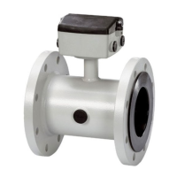
SITRANS F M
Electromagnetic flowmeter
type MAG 1100, DN 2 - DN 100 1/12" - 4"
083R9017
083R9017
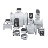
Siemens Flow Instruments SITRANS F M electromagnetic flowmeters consist of a sensor and a
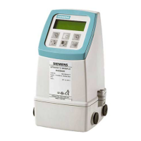
transmitter. These instructions only describe the sensor installation. For further information on the
transmitter installation, please refer to the SITRANS F M handbook.
Introduction
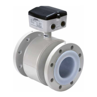
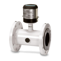
MAG 1100/6000, MAG 1100/5000 and MAG 1100/6000I, compact/separate
Dimensions and
weight
SFIDK.PI.027.G7.52Order no.: FDK-521H0928
s
ENGLISH
DEUTSCH
FRANÇAIS
DANSK
DN A
1
)B
1
)A
2
/A
2
4
)B
1
DD
i
2
)D
i
(PFA) D
p
D
G
Weight
3
)
[mm] [mm] [mm] [mm] [mm] [mm] [mm] [mm] [mm] [kg]
2 161 186 315 340 48.7 2 17.3 34 2.2
3 161 186 315 340 48.7 3 17.3 34 2.2
6 161 186 315 340 48.7 6 17.3 34 2.2
10 161 186 315 340 48.7 10 10 13.6 34 2.2
15 161 186 315 340 48.7 15 16 17.3 40 2.2
25 169 201 323 354 63.5 25 26 28.5 56 2.7
40 179 221 333 375 84.0 40 38 43.4 75 3.4
50 188 239 342 393 101.6 50 50 54.5 90 4.2
65 198 258 351 412 120.9 65 66 68.0 112 5.5
80 204 270 357 424 133.0 80 81 82.5 124 7.0
100 217 296 370 450 159.0 100 100 107.1 145 10.0
1
) 14.5 mm/0.57" shorter when the AISI terminal box is used. (high temperature 200°C (390°F)).
2
) DN 2-3 Zirconium (Z
r
0
2
), DN 6-100/1/4"-4" Ceramic (Al
2
O
3
).
3
) With transmitter MAG 5000 or MAG 6000 installed, weight is increased by approximately 0.8 kg (1.8 lb).
4
)A
2
is 3 mm(0.12") shorter than A
1
.
Size A
1
)B
1
)A
2
/A
2
4
)B
1
DD
i
2
)D
i
(PFA) D
p
D
G
Weight
3
)
[inch] [inch] [inch] [inch] [inch] [inch] [inch] [inch] [inch] [lbs]
1
/
12
6.34 7.33 12.40 13.39 1.92 0.08 0.68 1.34 4.8
1
/
8
6.34 7.33 12.40 13.39 1.92 0.12 0.68 1.34 4.8
1
/
4
6.34 7.33 12.40 13.39 1.92 0.24 0.68 1.34 4.8
3
/
8
6.34 7.33 12.40 13.39 1.92 0.39 0.39 0.53 1.34 4.8
1
/
2
6.34 7.33 12.40 13.39 1.92 0.59 0.63 0.68 1.57 4.8
1 6.66 7.92 12.72 13.94 2.50 0.98 1.02 1.12 2.20 4.9
1½ 7.05 8.70 13.11 14.76 3.31 1.57 1.50 1.71 2.95 7.5
2 7.40 9.41 13.47 15.47 4.00 1.97 1.97 2.15 3.54 9.2
2½ 7.80 10.16 13.82 16.22 4.76 2.56 2.60 2.68 4.41 12
3 8.03 10.63 14.06 16.70 5.24 3.15 3.19 3.25 4.88 15
4 8.54 11.65 14.57 17.72 6.26 3.94 3.94 4.22 5.91 22
Technical Documentation (handbooks, instructions, manuals etc.) on the complete product
range SITRANS F can be found on the internet/intranet on the following links:
English:
http://www4.ad.siemens.de/WW/view/en/10806951/133300
Important note!
for compact installations
with the MAG 6000I,
transmitter to be sup-
ported to avoid tension
on sensor part.






 Loading...