VGDSeriesDoubleValves TechnicalInstructions
DocumentNumberCC1N7631us
November08,2017
SiemensAGBuildingTechnologiesDivision Page 9
Gasflowcharts
100 2 3 4 5 7 1000 2 3 4 5 7 10000 2 3 4 5 7 100000 2 3
7 100 2 3 4 5 7 1000 2 3 4 5 7 10000 2 3 4 5 7 100000 2
7 100 2 3 4 5 7 1000 2 3 4 5 7 10000 2 3 4 5 7 100000 2
100 2 3 4 5 7 1000 2 3 4 5 7 10000 2 3 4 5 7 100000 2 3
3 4 5 7 10 2 3 4 5 7 100 2 3 4 5 7 1000 2 3 4 5 7
cf/h Natural gas 0.64
1
cf/h Propane gas 1.52
2
cf/h Butane gas 2.00
3
cf/h Air 1.00
4
m3/h Air 1.00
4
Sp. Gr.
1,000
700
500
400
300
200
100
70
50
40
30
20
10
7
5
4
3
2
1
0,7
0,5
0,4
0,3
0,2
1,000
700
500
400
300
200
100
70
50
40
30
20
10
7
5
4
3
2
1
0,7
0,5
0,4
´´W.C. mbar
Pressure drop p
7631t06us/1215
VGD20...
GD40...
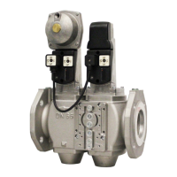
Figure3.Sizingdoublevalves
Assumptions:
1)Pressuredownstreamofvalveisatmospheric
2)Maximumgastemperatureof140°F
3)Valveinfullyopenposition
NOTE:
PressuredropistotaldropacrossbothvalveswhenusingaSKPx5.xxxUactuator,
withorwithoutanAGA66.
CAUTION:
DonotoversizevalvesequippedwithregulatingactuatorsSKP2x.xxxU,
SKP5x.xxxUorSKP7x.xxxU.Oversizingmaylimitturndownandcouldcause
oscillations.
 Loading...