Do you have a question about the Siemens VVF Series and is the answer not in the manual?
This document provides comprehensive instructions for the installation, operation, and maintenance of Siemens VVF and VXF series valves, which are designed for various applications, including heating and cooling systems.
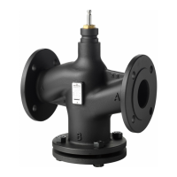
The VVF and VXF series valves are primarily used for controlling the flow of media within pipework. They are available in different configurations (2-way and 3-way) and are designed to be integrated with actuators for automated control. The valves are suitable for a range of temperatures and pressures, as indicated by their specific model numbers (e.g., VVF43, VVF53, VVF63, VXF43, VXF53, VXF63). The flow direction is clearly marked on the valve body, ensuring correct installation. The "A" port typically represents the inlet, "AB" the outlet, and "B" an alternative flow path for 3-way valves. The document illustrates various flow configurations, including A-AB, A-B, and AB-A, depending on the valve type and intended application.
The valves are designed to operate within specific temperature ranges. For temperatures below 0 °C, specific models like VVF43..K and VVF53..K (for DN 200 and above) are recommended. For temperatures below -5 °C, models such as VVF43/53/63.. and VXF43/53/63.. (for DN 65 and above, Series D or A) are specified, indicating their suitability for colder environments.
The document provides a detailed table for maximum tightening torques (Mmax) for flange connections, which is crucial for ensuring a secure and leak-free installation. The torque values vary based on the nominal diameter (DN) and nominal pressure (PN) of the valve. For example:
These torque values are critical for proper sealing and preventing damage to the flange connections. The installation instructions emphasize a three-step tightening process for flange screws: 25% M, 50% M, and finally 100% M, applied crosswise. A final retightening to the maximum torque (M) is recommended after the operating temperature has been reached.
The document also specifies minimum clearances for installation. For horizontal pipe runs, a minimum distance of L ≥ 0.4 m ... ≥ 10 x DN is required for straight pipe sections before the valve. For vertical installations, a minimum clearance of ≥ 100 mm from the valve body to any obstruction is necessary, with a recommended ≥ 200 mm for optimal access.
The valves are designed for integration into various systems, including those requiring precise flow control. The clear markings for flow direction (A, B, AB) ensure correct orientation during installation, which is vital for the proper functioning of the system. The compatibility with different actuators (indicated by the need to install the actuator after the valve) allows for automated control, making these valves suitable for modern building management systems. The document highlights the importance of ensuring the valves are fully open before filling the plant, which prevents damage and ensures proper system operation.
Maintenance and commissioning of these valves must only be performed by qualified personnel. This ensures safety and proper functioning. Key maintenance-related instructions include:
Overall, the document emphasizes safety, proper installation techniques, and qualified personnel for all stages of the valve's lifecycle, from mounting to maintenance.
| Brand | Siemens |
|---|---|
| Model | VVF Series |
| Category | Control Unit |
| Language | English |