User Guide v.1.0 Siensor UNIC
3. Device Description
In most cases RS-232 and RS-485 interfaces are used to configure LLSs, on this account Siensor UNIC
supports operation both via RS-232 and RS-485 interfaces. The device is fitted with the switch on the front
panel to select an operating mode (see 2 in Fig. 3.1).
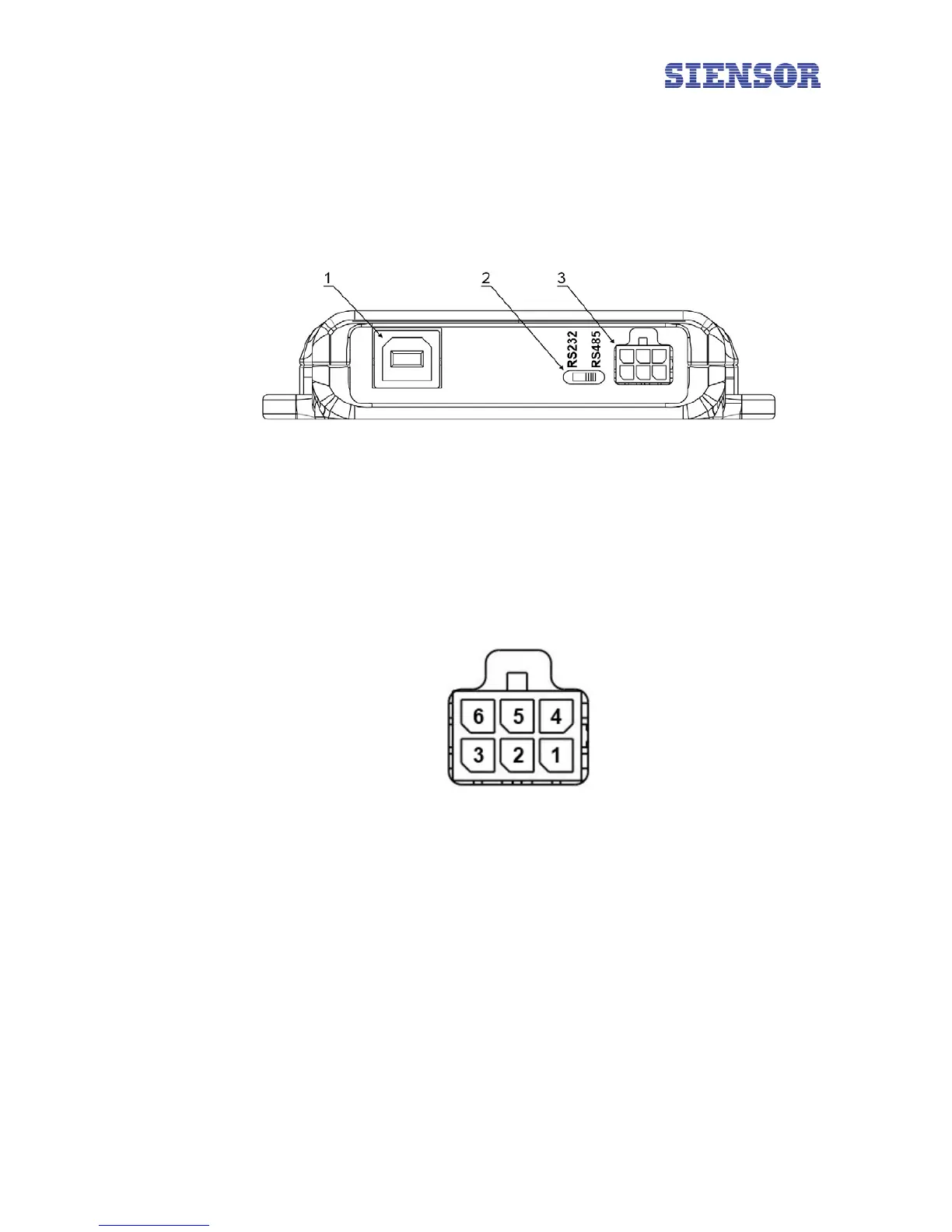
Fig. 3.1 General view of Siensor UNIC – front panel
The numbers in figure 3.1 show:
1 – the USB interface for connection of the device to a PC
2 – the device mode switch (RS-232 or RS-485. The figure illustrates the device in the RS-485 operating
mode)
3 – the interface for connection of LLS
Fig. 3.2 Interface pins assignment to connect the LLS
The numbers in figure 3.2 show:
1 – GND
4 – output voltage of +12В
2 – RS-232 TX (Out)
5 – RS-232 RX (In)
6 – RS-485 A
3 – RS-485 B
6