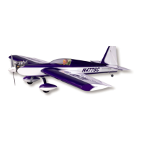
and progressively enlarge it to accept the needle valve body
through the fuselage and into the carburetor. The finished hole
should be just a little larger than the diameter of the needle valve
body.
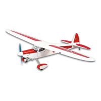
With the engine in place in the nose, install the manifold pipe and
the muffler to check for the final fit. Install the needle valve into the
carburetor. Make any final adjustments to these openings. You will
likely need to add a wire needle valve extension to clear the
fuselage side. The needle valve will have a hole in its center with
a setscrew for this purpose. Use the engine manufacturer’s
included needle valve extension wire (the Magnum .52 did not
include one) or make one from 1/16” dia. music wire.
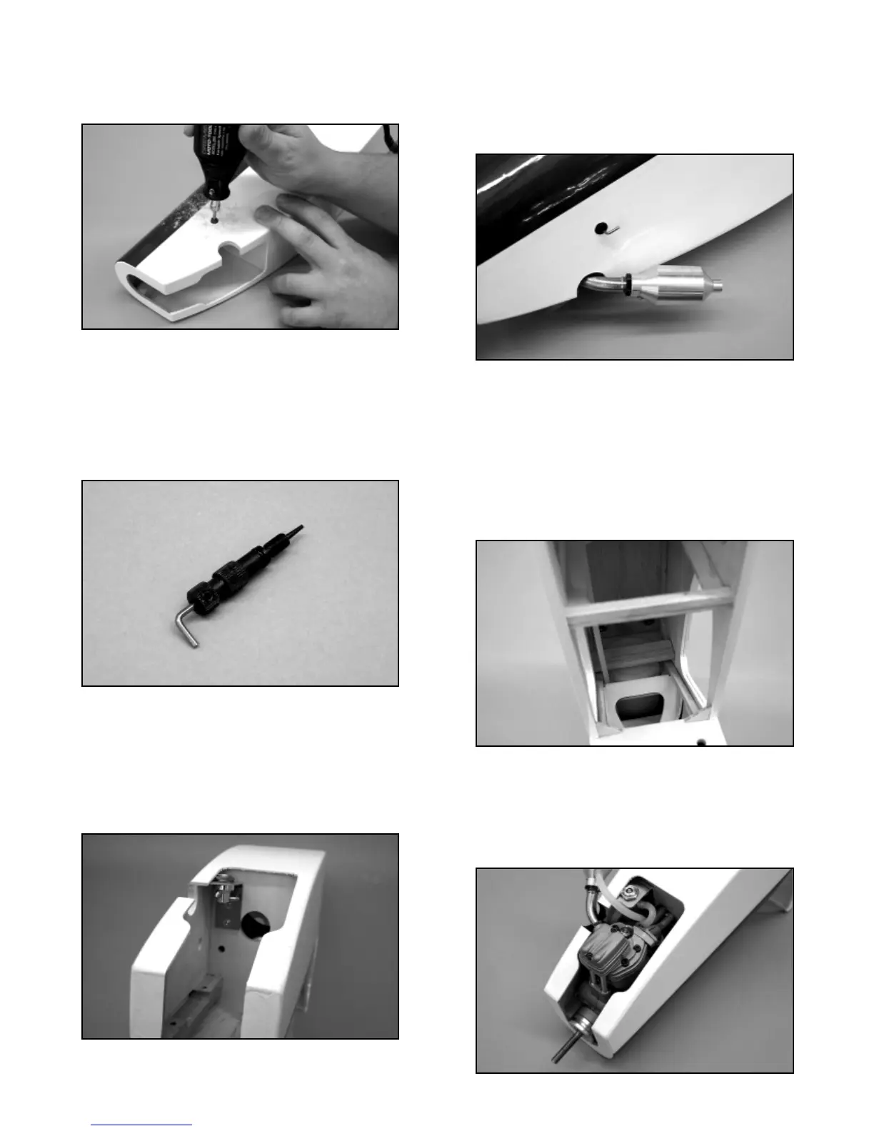
❑ 8) If you are using the optional fueling valve, now is the time to
mount it. We mounted ours on the left side of the firewall (opposite
the throttle linkage), facing straight down. This works very well and
eliminates the need for another hole in the side of the fuselage for
the fueling probe. Make and install the aluminum mounting
bracket to the firewall (with the fuel valve in place) and mark the
location of the required #2 x 3/8 mounting screws onto the firewall.
Mount the bracket to the firewall.
❑ 9) The engine compartment has already been fuel-proofed at
the factory. However, the exposed wood edges of the muffler and
needle valve openings should now be coated to make them fuel
proof as well. We suggest using clear dope or epoxy resin to seal
the exposed wood. To make this job look totally complete and
custom, try using flat white or flat black dope or other fuel-proof
paint.
❑ 10) The fuel tank is now installed. Apply a bead of silicon
sealer around the neck of the tank and install it into the fuel tank
compartment, through the top of the fuselage. Press the neck into
the hole in the firewall. Included in the kit contents is a balsa piece
measuring 5/16” x 3/4” x 3-3/16”. This is the rear tank retainer.
Position the retainer directly behind the tank, between the fuselage
sides. Apply a couple of drops of thin CA glue to each side of the
retainer to hold it in place. Should you ever need to remove tank,
the retainer can be easily popped loose and the tank can be
removed.
❑ 11) Apply a little thread-locking compound to the threads of the
3.5 x 20mm mounting bolts. Install the lock washers onto each
bolt, followed by the larger flat washers. Install the engine and
aluminum rails into the engine compartment. Slip the four bolts
(with washers) into the oblong holes in the aluminum rails. Thread
the bolts into their blind mounting nuts and tighten the bolts firmly
11