to the wood rail mounts - be sure to maintain the 1/16” - 3/32”
spinner backplate clearance. Use medium fuel tubing (not
supplied) to make the required connections between the engine
and fuel tank and the vent line and the muffler manifold pressure
nipple.
The throttle linkage will be made during the radio installation
phase of these instructions. This completes the engine and fuel
tank installation.
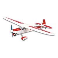
SPINNER ASSEMBLY:
Locate the white SIG spinner assembly from the kit contents. This
spinner is easy to install, lends a great look to your finished
RASCAL FORTY ARF and is ready to use with typical APC
propellers for engines in the size range for this model!
Start by choosing the correct adapter ring for your particular
engine. The fit should be firm (not loose) over the engine’s prop
shaft. Slip the spinner backplate onto the prop shaft and onto the
adapter ring. The propeller is installed next using the engine’s
washer and nut to secure it. The spinner cone is now installed over
the prop and into the recess in the backplate. The spinner is then
secured in place using the provided screws. Be sure to snug these
screws firmly in place but do not over-tighten them.
FUSELAGE AND TAIL GROUP ASSEMBLY:
Note that the elevators have been pre-hinged to the horizontal
stabilizer. Flex the elevators up and down a few times to free their
movement. However, the rudder has not
been pre-hinged and will
have to be hinged during the following assembly steps.
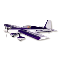
❑ 1) The fuselage has been built and covered with a few
openings that now need to be opened up and cleared to complete
assembly. These are the two landing gear bolt holes on the bottom
of the fuselage and the three pre-drilled holes for mounting the
tailwheel assembly, at the bottom rear of the fuselage.
Last, you will need to remove the covering over the rudder and
elevator pushrod exits. These are located on each side of the
fuselage, beneath the horizontal stabilizer. A sharp #11 blade is
perfect for this step. If necessary, use a covering iron to re-seal the
covering around these openings.
❑ 2) From the kit contents, locate the horizontal stabilizer and
elevator set and the vertical fin and rudder set. Join the wing
panels together and bolt the wing to the fuselage. Set the airplane
on a flat surface that allows you to easily view it from both the
front and rear. Use 5-minute epoxy to glue the horizontal
stabilizer/elevator assembly to the fuselage. Apply glue liberally to
the stabilizer saddle at the top rear of the fuselage. Also apply
glue to the bottom of the stabilizer where it contacts the fuselage.
Carefully center the stabilizer to the fuselage, making sure it is
centered in top view as well as in front and rear view. Use weights
or pins to hold the stabilizer in this aligned position until the epoxy
cures. Wipe off any excess glue with alcohol.
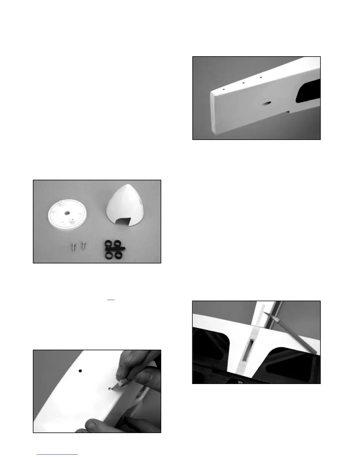
❑ 3) Remove the rudder from the vertical fin, including the three
hinges. The rudder will be hinged later. The vertical fin is now
glued in place to the top of the stabilizer. Begin by trial-fitting the
fin into the slot on the top of the stabilizer. Test the fit, making sure
that the bottom of the fin sits flat and in full contact to the stabilizer.
Trim or sand the bottom of the fin tab until the fin sits fully in place
on top of the stabilizer. Holding the fin in place, use a sharp pencil
to trace around its forward bottom fairing, where it extends forward
of the stabilizer and on to the top of the fuselage. Remove the fin
and use a sharp knife to remove the covering from just inside of
the pencil marks just made.
Use 5-minute epoxy to apply glue to the bottom of the vertical fin,
including the tab that fits into the top of the stabilizer. Press the fin
in place into the top of the stabilizer slot and wipe off any excess
glue with alcohol. Use strips of tape and/or pins to align the fin at
90
O
to the stabilizer. View the airplane from the front, making sure
the fin is perfectly upright and aligned to the stabilizer, wing, and
fuselage without tilting one way or the other. With the fin now held
12