in position, allow the glue to set.
When the epoxy has set, remove the wing from the fuselage.
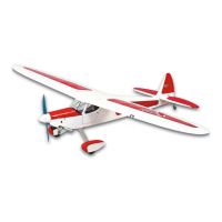
❑ 4) From the kit contents, locate the bag containing the pre-
assembled SIG tailwheel assembly. Note that the bottom rear of
the fuselage has a plywood hardpoint beneath the covering for
mounting the tailwheel bracket.
Mount the bracket to the bottom rear of the fuselage, using three
#4 x 1/2” screws provided. Snug the screws securely.
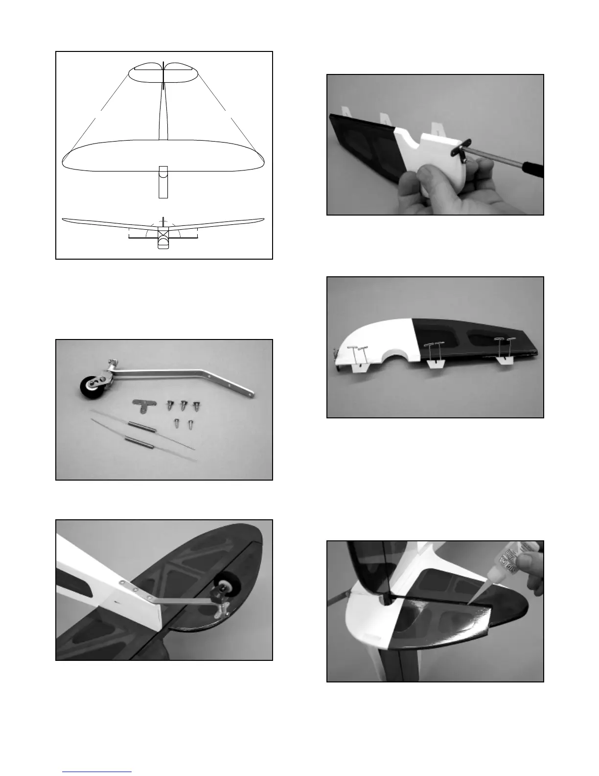
❑ 5) Attach the aluminum spring centering horn to the bottom
leading edge of the rudder, as shown, using two #2 x 3/8” screws.
Note that the bottom leading edge of the rudder has hardwood
beneath the covering as a hardpoint for the screws. Position the
front edge of the horn 1/8” behind the leading edge of the rudder.
Use the aluminum centering horn to first mark the required
locations for the screw holes and then use a 1/16” drill bit to make
two guide holes into the bottom of the rudder. Secure the horn in
place with the screws.
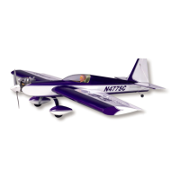
❑ 6) The rudder is now hinged to the vertical fin and fuselage.
Slide the three CA hinges in place into the pre-slotted rudder,
centering them. Use pins in the center of each hinge to keep them
centered when pressing them into the hinge slots in the vertical fin.
Press the rudder hinges in place into the hinge slots in the vertical
fin. Adjust the rudder position to the fin and remove the pins. Use
a piece of masking tape to hold the rudder hard over to one side
or the other, exposing centers of the hinges. Use thin CA glue and
apply 3 - 4 drops to each hinge. Remove the tape and use it to
hold the rudder hard over to the opposite side and again apply
3 - 4 drops of CA glue to each hinge. Remove the tape, center the
rudder by hand and allow at least 10 minutes for the CA glue to
fully wick into and set each hinge. Flex the rudder back and forth
to free its movement. The rudder is now hinged in place.
NOTE: The two tailwheel centering springs are not attached until
after the rudder servo has been installed, tested and centered.
❑ 7) From the kit contents, locate the following parts: Formed
13