I. 2-STROKE THROTTLE PUSHRODS:
The throttle pushrod for typical 2-stroke engines is the traditional
push-pull type, cut to length, with metal control links at each end.
a) From the kit contents, locate the 16” length of inner nylon
pushrod tubing, two M2 x 7/8” threaded studs and two metal
control links. Use an electric drill to thread one of the studs about
1/4” into one end of the nylon pushrod. Thread a metal control link
onto the threaded stud and insert the unprepared end of the
pushrod into the tube pushrod housing protruding from the firewall.
Snap the metal control link onto the throttle arm of your engine.
b) Look at your engine to determine which direction the
throttle arm must travel to be in the full throttle position - using the
transmitter, set the direction of travel for the throttle servo
accordingly.
c) Thread the remaining stud into the remaining metal control
link. Snap the link onto the outermost hole in throttle servo output
arm. Use a marker pen to mark the nylon pushrod where it should
be cut and still accept about 1/4” of the threaded stud. Disconnect
the metal link from the servo arm and remove the pushrod from the
fuselage tube. Cut the tubing at the mark just made. Unthread the
stud from the metal link and use the electric drill to thread the stud
into the end of the pushrod, about 1/4”.
d) Re-insert the pushrod into the fuselage from the firewall.
Thread the metal link onto the stud in the servo compartment.
Connect the front metal link to the throttle pushrod arm on the
engine and turn on the radio system. Adjust the metal link in the
servo compartment as needed to achieve full and low throttle
settings with the transmitter. Note that in some cases, this may
require moving the metal link on the servo output arm. As done
with the elevator and rudder pushrods, apply a drop of thin CA glue
to the threads on the stud and control link at the engine end of the
pushrod to keep the pushrod from twisting. Last, apply a drop or
two to the firewall where the throttle tube housing exits, to lock the
outer tube in place.
II. 4-STROKE THROTTLE PUSHRODS:
The throttle pushrod for 4-stroke engines is almost exactly the
same as it is for 2-stroke engines. The difference has to do with
the rear throttle arm location on most 4-stroke engines. Because
of this, the pushing and pulling of the pushrod, from the rear, must
be changed to get the same action from the front. To do this, it is
necessary to make a pushrod - in the engine compartment - that
reverses the action of the servo at the engine throttle arm. We do
this by replacing the 7/8” threaded stud with a longer wire pushrod
that’s threaded at one end. Also, it is important that the engine
throttle arm is facing upwards, toward the head of the engine. This
throttle arm position allows it to be more easily accessed for
attachment of the metal control link. Every engine we tested for
this model allowed repositioning of the throttle arm.
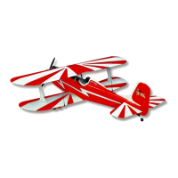
a) From the kit contents, locate the 16” inner nylon pushrod, a
M2 x 7/8” threaded stud, a metal control link, a 10” metal pushrod
wire (threaded at one end) and a metal solder link (no internal
threads). Use the electric drill to thread the 10” metal pushrod into
one end of the nylon pushrod - about 1/4”. You will also need a
soldering iron and solder.
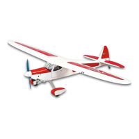
b) With the 10” pushrod threaded into the nylon pushrod,
measure 3” from the front face of nylon pushrod, out onto the metal
pushrod and mark the point with a marker pen. This is the point
where you will begin to make a 180
O
bend in the metal pushrod
wire. The diameter of this bend should be the same as the
distance from the center of the pushrod exit in the firewall to the
hole in the engines throttle arm. For example, this distance
measured 1” on our Magnum .52. Therefore, we bent the pushrod
180
O
, leaving a 1” spacing.
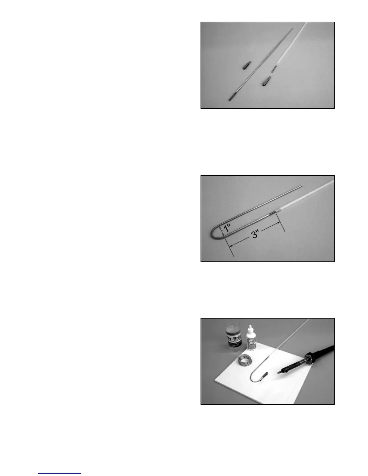
c) The end of the wire that reverses back toward the nylon
tube is now cut, leaving just enough wire to slip the solder link in
place. Cut the wire with a carbide cut-off wheel and slip the solder
link in place. Solder the link in place to the wire with the arms of
the link facing toward each side of the wire in top view. This
position allows the two arms of the link to be spread and placed
onto the throttle arm.
d) Insert the unprepared end of the nylon pushrod into the
tube protruding from the firewall, all the way back to the servo
compartment. Use needle nose pliers or hemostats to connect the
solder link to the throttle arm on the engine. From the servo
compartment, test the action of the pushrod and adjust the bend
as needed to obtain a smooth throttle movement.
17
 Loading...