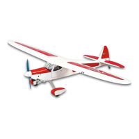
e) Thread the M2 x 7/8” stud into the remaining metal control
link. Attach the link to the outermost hole in the throttle servo arm.
Turn on the radio system. With the action of the throttle pushrod
reversed, full “low” throttle is obtained by pulling the pushrod back
in the servo compartment, as far as possible. Pull the pushrod
back and place the servo output arm onto the servo in the correct
full “low” throttle position. Mark the nylon pushrod with a marker
pen where it will be cut and still accept about 1/4” of the threaded
stud. Remove the nylon pushrod from the fuselage and cut it off
at the mark just made.
f) Remove the M2 x 7/8” threaded stud from the metal link and
use an electric drill to thread one end of it into the nylon pushrod,
about 1/4”. Re-insert the pushrod into the tube in the firewall, all
the way back into the servo compartment. Thread the metal link
back onto the end of the stud and attach the link to the servo
output arm. Adjust the link as needed on the stud to fit perfectly
with the “low” throttle position of the output arm. Test the throttle
linkage with the radio system, making any adjustments needed for
smooth action. Many radio systems available today, such as the
Airtronics™ RD-6000 Sport system have an “EPA” or End Point
Adjustment feature. This feature allows electronic adjustment of
the total movement of any servo. EPA can be used to adjust the
movement of the throttle servo as required.
❑ 6) The battery pack will be installed when the correct Center
of Gravity is established. For now the radio installation is
complete. Be sure to install and tighten the output retaining
screws in each servo.
CONTROL SURFACE TRAVEL:
The following control surface movement suggestions will provide
your RASCAL FORTY with smooth, predictable flight
characteristics. We suggest that you start with these movements
and adjust them later to suit your particular style of flying. Note
that the rudder and elevator measurements are taken from the
widest part of the surface at the trailing edge. The aileron
measurements are taken at the inboard trailing edge.
AILERONS: 3/4” UP – 3/4” DOWN
ELEVATORS: 3/4” UP - 3/4” DOWN
RUDDER: 1” LEFT - 1” RIGHT
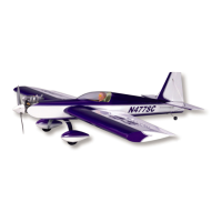
SIDE WINDOW INSTALLATION:
From the kit contents, locate the small bag containing the molded
clear plastic side windows. The side windows are molded to mount
and fit into the fuselage window frames, from the inside. Use
scissors to cut out each window, leaving about 1/8” of plastic
around the edges for a gluing surface.
We suggest using 5-minute epoxy or RC-56 glue to mount these
windows. Do not use thin CA glue for this purpose! Apply a thin
bead of glue around the edges of the plastic window and press it
in place from the inside of the fuselage. Use a few small pieces of
tape to hold the window in place until the glue sets. A little alcohol
will safely clean off any excess glue from the windows.
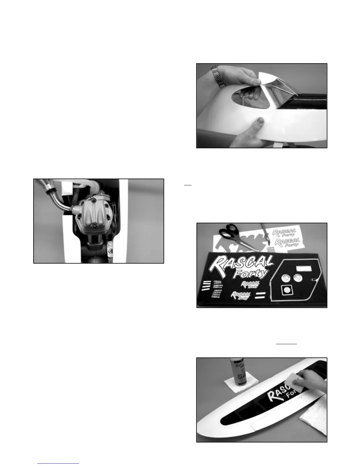
DECAL APPLICATION:
The decals supplied with your RASCAL FORTY ARF kit are high
quality Mylar
®
with an extremely aggressive adhesive. These are
not
die-cut decals and must be removed from the sheet with a
hobby knife and a sharp #11 blade or sharp scissors. In the case
of the large doorframe outline, we suggest that you cut this decal
out on both sides of the frame outline, in one piece. If you are
careful, this isn’t as difficult as it sounds. Application of this decal
is easy if you follow the methods described below.
We suggest the following method to accurately apply the larger
decals in this kit. Carefully cut out the decal and lift it off the sheet
with tweezers. Use a product like SIG Pure Magic Model Airplane
Cleaner, Fantastic
®
‚ or Windex
®
to spray the area of the model that
will receive the decal. Then spray the adhesive side of the decal
as well. Lightly position the decal in place on the model. The liquid
18