Do you have a question about the SIGLENT SDS2204X Plus and is the answer not in the manual?
Explains safety symbols and terms used in the manual and on the instrument.
Details the need for adequate airflow around the instrument for cooling.
Outlines the instrument's AC power specifications and auto-adaptation to line voltage.
Explains the importance of proper power cord use and safety ground connections.
Advises on operating the instrument only for specified purposes and handling damage.
Explains two methods for powering on: 'Power on Line' and 'Power on by Manual'.
Describes how to turn off the oscilloscope and the note about full power down.
Explains probe safety features and precautions against electric shock.
Details the procedure for compensating the probe to match the oscilloscope's input channel.
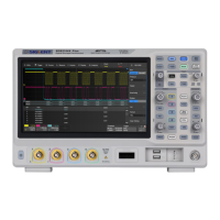
Provides an overview of the oscilloscope's front panel components and their functions.
Explains how to control vertical settings using channel buttons and the vertical knob.
Details how to adjust horizontal scale, zoom, roll, and trigger delay.
Explains the trigger setup, mode, and level adjustment controls.
Describes the button to switch between acquisition Run and Stop states.
Explains how the Auto Setup button optimizes waveform display settings.
Guides on enabling or disabling analog and digital channels.
Explains how to set vertical scale, offset, and other channel parameters.
Determines signal acquisition and processing modes, including interpolation and memory depth.
Explains the trigger function for acquiring waveforms of interest and stable display.
Guides on setting trigger level, mode (Auto, Single, Normal), and other parameters.
Defines the voltage level that must be crossed for a trigger event to occur.
Determines how the oscilloscope acquires waveforms (Auto, Normal, Single).
Covers various trigger types like Edge, Slope, Pulse, Video, Window, etc.
Triggers based on the slope (rising, falling) of a signal edge.
Triggers when a slope crosses specific upper and lower trigger levels.
Triggers on pulses within or outside a specified width.
Triggers on specific lines or fields of standard video signals.
Triggers when a signal enters or leaves a defined window region.
Triggers based on the time difference between neighboring signal edges.
Covers triggering and decoding of I2C signals, including signal settings and trigger conditions.
Covers triggering and decoding of SPI signals, including signal settings and trigger conditions.
Covers triggering and decoding of UART signals, including signal settings and trigger conditions.
Covers triggering and decoding of CAN signals, including signal settings and trigger conditions.
Covers triggering and decoding of LIN signals, including signal settings and trigger conditions.
Covers triggering and decoding of FlexRay signals, including signal settings and trigger conditions.
Covers triggering and decoding of CAN FD signals, including signal settings and trigger conditions.
Covers triggering and decoding of I2S signals, including signal settings and trigger conditions.
Covers triggering and decoding of MIL-STD-1553B signals.
Calculates power dissipated during the switching period and includes deskew calibration.
Determines the response speed of the output voltage to load changes.
Measures how regulators suppress ripple noise across different frequency ranges.
Tests overall power supply efficiency by measuring input and output power.
Runs tests for screen, keyboard, and LEDs to check instrument functionality.
Initiates the self-calibration program for optimal performance and precision.
Allows oscilloscope control via a web browser using its IP address.
| Brand | SIGLENT |
|---|---|
| Model | SDS2204X Plus |
| Category | Test Equipment |
| Language | English |