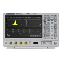
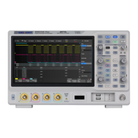
Do you have a question about the SIGLENT SDS2504X Plus and is the answer not in the manual?
Explains safety symbols and terms used in the manual and on the instrument.
Details operating conditions for temperature, humidity, and altitude.
Describes the instrument's AC power input voltage and frequency ranges.
Explains how to connect the power cord and safety ground for electrical safety.
Provides safety precautions for using oscilloscope probes, focusing on preventing electric shock.
Details the procedure for compensating a probe to ensure accurate measurements.
Explains how to use the vertical controls, including channel buttons, math, and reference functions.
Details the horizontal controls for adjusting scale, zoom, roll mode, and trigger delay.
Describes the trigger control functions, including setup, auto mode, single mode, and level adjustment.
Explains how to set up trigger parameters like level, mode (Auto, Single, Normal), and source.
Details the importance of setting a correct trigger level and how the system automatically sets it for some sources.
Describes the different trigger modes (Auto, Normal, Single) and their use cases for waveform acquisition.
Overviews various trigger types available, such as Edge, Slope, Pulse, Video, and Serial.
Describes zone trigger, allowing users to define areas on the waveform for isolating specific events.
Details I2C signal setup, triggering conditions, and decoding results.
Details SPI signal setup, triggering conditions, and decoding configuration.
Details UART signal setup, triggering conditions, and decoding configuration.
Details CAN signal setup, triggering conditions, and decoding configuration.
Details LIN signal setup, triggering conditions, and decoding configuration.
Details FlexRay signal setup, triggering conditions, and decoding configuration.
Details CAN FD signal setup, triggering conditions, and decoding configuration.
Details I2S signal setup, triggering conditions, and decoding configuration.
Details MIL-STD-1553B signal setup, triggering, and decoding configuration.
Guides on selecting measurement sources and parameters, adding/removing them, and using favorite tabs.
Introduces FFT for frequency spectrum analysis, with frequency on the horizontal axis and options for logarithmic scaling.
Covers enabling/disabling tests, selecting sources, rules, masks, and Pass/Fail operations.
Explains methods to create masks automatically or using the Mask Editor tool.
Details the Pass/Fail rules: All In, All Out, Any In, and Any Out, specifying conditions for passing or failing.
Details power quality analysis parameters like active power, reactive power, power factor, and voltage/current crest factors.
Explains current harmonics analysis using FFT to get harmonic components of input current.
Describes inrush current, a large current surge occurring when switching on a power supply.
Explains switch loss analysis for calculating power dissipated during switching periods and deskew calibration.
Defines slew rate as the change rate of voltage or current during switching.
Describes modulation analysis for observing control pulse signals of switching devices like MOSFETs.
Explains output ripple as a parameter for evaluating DC power supply quality, representing output DC voltage quality.
Defines turn-on time (reaching 90% output) and turn-off time (falling to 10% output) analysis.
Details transient response analysis to determine power supply output voltage response speed to load changes.
Explains PSRR test for determining how regulators suppress ripple noise across different frequency ranges.
Describes power efficiency analysis for testing overall efficiency by measuring input and output power.
Covers configuration settings for bode plot, including DUT connection, AWG connection, and sweep parameters.
Explains how to analyze bode plot curves using data lists, cursor measurements, and automatic measurement functions.
Introduces the built-in arbitrary waveform generator (AWG) functionality, its basic waveforms, and output capabilities.
Details self-test procedures for screen, keyboard, and LED tests to check for hardware issues.
Explains how to perform self-calibration for optimal performance and precise measurements, especially after temperature changes.
Details controlling the oscilloscope via a web browser by inputting its IP address.
Addresses common issues like no display, no waveform, unstable display, touch screen issues, and USB recognition.
| Brand | SIGLENT |
|---|---|
| Model | SDS2504X Plus |
| Category | Test Equipment |
| Language | English |

