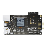
Do you have a question about the Silicon Laboratories EFR32xG21 Wireless Gecko and is the answer not in the manual?
Lists key features of the ARM Cortex-M33 CPU platform, memory, I/O pins, and communication interfaces.
Covers hardware support for AES encryption, decryption, and authentication modes for security operations.
Lists the multiple timers included in EFR32xG21, such as RTCC, BURTC, TIMER, Systick, WDOG, LETIMER, PROTIMER.
Lists key features of the ARM Cortex-M33, including Harvard architecture, pipeline, instruction set, MPU, and power modes.
Explains how interrupt request (IRQ) lines connect to the Cortex-M33, including interrupt flags and enable bits.
Describes ARM TrustZone for restricting access to peripherals and memory regions based on CPU security attribute.
Explains the multilayer AMBA AHB bus matrix connecting master interfaces to AHB slaves, allowing simultaneous access.
Describes Flash memory, its capacity, page size, endurance, data retention, and programming capabilities.
Details SRAM memory for storing application data, executing instructions, and DMA transfers.
Explains the support for bit set, bit clear, and bit toggle access to most peripheral registers for modifying bit fields.
Details peripheral register access performance based on frequency, access type, and clock scaling.
Introduces the Radio Transceiver for tailoring radio operation, with access to transmit/receive data buffers and frame support.
Explains how the SYSCFG module controls RAM blocks, including enabling EM2/EM3 data retention, ECC, and cache.
Details flash write and erase operations, including page erase, mass erase, and programming operations.
Details how the instruction cache improves speed and power consumption by providing fast access to recently executed instructions.
Explains the SYSCFG block for configuring SRAM and contains interrupt flags for software use.
Describes how DMEM0, FRCRAM, and SEQRAM support one bit correction and two bit detection ECC.
Explains how to enable RAM wait states to ensure adequate response time when the Cortex-M33 runs faster than RAM.
Details the SYSCLK, HCLK, PCLK, LSPCLK, and HCLKRADIO clocks, and their prescaler settings.
Details how to lock control and command registers to prevent unintended software writes to critical clock settings.
Details the High Frequency Crystal Oscillator (HFXO) features, including optimization for 38.4 MHz crystals and start-up parameters.
Describes the HFRCO as a calibrated internal High Frequency RC oscillator with features like low start-up time.
Explains the DPLL which uses a reference clock to generate a desired clock frequency with features like fast lock time.
Details the Low Frequency Crystal Oscillator (LFXO) using an external 32.768 kHz crystal for accurate low-frequency clock.
Describes the LFRCO as an integrated low-frequency (32.768 kHz) RC oscillator for timing reference in low energy modes.
Details bus level security, including Cortex-M33, BMPU, PPU, and SMU roles in configuring security.
Explains how Cortex-M33 and other masters are tested for privilege level by PPU.
Describes how bus accesses are tested for security status by BMPUs and PPUs.
Explains ARM TrustZone for controlling accessible addresses by CPU, with security states and privilege levels.
Details how SMU configures secure and privileged attributes of all bus masters except the CPU.
Explains how SMU configures secure and privileged state of peripherals, and address validation.
Describes SMU ability to configure security attribute of memory, with 8 configurable regions.
Covers Cortex-M33 additional security features for controlling secure and privileged access.
Explains how SMU registers can be locked to prevent unintended modifications.
Details security features such as AES encryption/decryption, ECC, SHA, and True Random Number Generation.
Explains communication with the Secure Element Subsystem through the SE Mailbox using FIFO.
Details the five energy modes (EM0 to EM4) and possible transitions between them.
Describes requirements for entering EM1, EM2, EM3, and EM4 energy modes.
Explains how systems in EM2 and EM3 can be woken up to EM0 through interrupts or resets.
Details Brown Out Detectors ensuring minimum supply voltage, and their raw output visibility.
Explains EMU RMU's role in ensuring correct reset operation and connecting reset sources.
Explains the configurable logic feature enabling PRS channel to perform logic operations on producer signals.
Lists GPCRC features including programmable 16-bit polynomial, fixed 32-bit polynomial, and byte-level bit reversal.
Details the RTCC counter structure with main counter (RTCC_CNT) and pre-counter (RTCC_PRECNT).
Explains the three capture/compare channels available in RTCC for input capture or output compare.
Details the programming sequence for configuring and using the BURTC properly.
Details the BURTC counters: 32-bit main counter (BURTC_CNT) and 15-bit pre-counter (BURTC_PRECNT).
Explains how to prevent accidental writes to BURTC registers using the BURTC_LOCK register.
Details the Buffered repeat mode allowing buffered timer operation using TOPBUFF and REP1 registers.
Provides a guide for writing LETIMER configuration, enabling clock, writing values, and configuring PRS mode.
Details the counter modes: Up-count, Down-count, Up/Down-count, and Quadrature Decoder.
Details the compare functionality where the CCx_OC register matches the counter value.
Details single slope PWM output generation in up-count mode, including period, resolution, and duty cycle equations.
Details the configuration lock available to prevent software errors from making changes to the timer configuration.
Describes the Dead-Time Insertion unit suitable for motor control applications, enabling complementary PWM outputs.
Explains USART operation in asynchronous and synchronous modes, and lists supported protocols.
Details asynchronous operation, including frame format, data bits, stop bits, and parity bit calculation.
Details the transmit buffer as a multiple entry FIFO buffer, and its operation with TXDATA and TXDOUBLE registers.
Describes data reception enabled by RXEN, and how the receiver samples input for start baud detection.
Explains the I2C-bus using SDA and SCL lines for communication, including collision detection and arbitration.
Describes bus transaction initiation by transmitting a START condition (S) on the bus.
Explains ACMP configuration and control through ACMP_CFG, ACMP_CTRL, and ACMP_INPUTCTRL registers.
Explains IADC register access, noting that configuration registers can only be written while the module is disabled.
Describes triggering options for Single and Scan queues, including IMMEDIATE, TIMER, PRS, and trigger actions.
Details IADC gain and offset correction capabilities, using SCALEx registers and production calibration values.
Introduces GPIO pins organized into ports for pin configuration, manipulation, and routing for peripheral connections.
Lists GPIO features including individual pin configuration, drive modes, interrupts, and peripheral resource routing.
Provides an overview of the GPIO module, showing pin configuration and alternate functions.
Details pin configuration options including input/output modes, pull-up/down, slew rate, and filter settings.
Introduces the Linked Direct Memory Access (LDMA) controller for memory transfer operations independent of the CPU.
Explains the channel descriptor structure containing control word, source, destination, and link addresses.
Details how LDMA transfer errors are managed using interrupts and clearing error flags.
Explains arbitration determining which channel is serviced at any point in time.
Describes arbitration priority modes: fixed priority and round robin priority.
Introduces the watchdog timer's purpose: to generate a reset in case of system failure.
Lists WDOG features including clock sources, timeout period configuration, and interrupt options.
Explains how the watchdog is enabled, configured, and reset.
| Brand | Silicon Laboratories |
|---|---|
| Model | EFR32xG21 Wireless Gecko |
| Category | Computer Hardware |
| Language | English |