GB/IE/NI/CY/MT 15
If the specified distances can not be main-
tained, the device may not be mounted.
When drilling, make sure that you do not
damage concealed power lines!
Drill two holes with a 6 mm drill and insert the
supplied wall dowels
J
into them.
Screw the fastening screws
I
into the wall
dowels
J
. Each screw
I
shall protrude to
about 10 mm.
Place the heater onto the fastening screws
I
(see Figure 5).
5
Now move the heater to the right and then down.
4.2 Installation in the bathroom
The device should not be mounted directly
above the connection box/wall socket.
The power supply cable should not hang in
front of the air outlet
G
.
Please carry out all electrical connection and
installation works in accordance with the relevant
national and regional regulations.
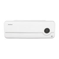
Hang the device onto the wall. The device’s air
outlet
G
should be at the bottom. Use the do-
wels
J
and screws
I
included in the delivery.
Please note: Make sure that the wall can bear
weights of at least 4.1 kg.
Please note: You may probably need a climbing
aid (e.g. a ladder) to be able to carry out the
installation.
The distance between the holes must be 31.5 cm
(see Figure 6).
6
The distance to the walls must be at least 30 cm.
The distance to the ceiling must be at least 45 cm.
The distance to the bathtub / shower tray should
not be less than 60 cm (see figure 8).
 Loading...