GB
12
Dust Extraction
1. Optimal dust extraction is achieved by connecting a dust extraction system or vacuum cleaner to
theDustExtractionPort(39).Adustportadaptor(notsupplied)mayberequiredtohelpconnect
the dust extraction system to the Dust Port
2. TheDustCollectionBag(26)tsdirectlyontotheDustExtractionPortusingaspringclip
3. ForefcientDustBagoperation,emptythebagwhenitisnomorethanhalffull,whichallows
betterairowthroughtheDustBag
Transportation
1. When transporting or storing the saw, ensure the cutting head is latched down with the Cutting
Head Latching Pin (28) and all bevel and mitre locks are in place
2. DO NOT carry the saw holding movable parts as this may cause injury
3. Ifthesawismountedtoabenchorsupport,ensurethexingsareremovedandthesawisfree
to move
4. If the saw is mounted to a portable board, ensure the board is unclamped from the workbench or
support so the saw is free to move
5. When moving or transporting the saw, always keep it upright
Fitting & removing the Blade
WARNING: Nevertanduseabladethatisvisiblydamaged,deformedorhasdullor
missing teeth.
WARNING: ALWAYS ensure the tool is disconnected from mains power when removing and
replacing blades or accessories on the saw.
WARNING: Wear gloves when handling blades.
WARNING: Never attempt to use a blade larger than the stated capacity of the saw, as it might
come into contact with the blade guards. Never use a blade that is too thick to allow the outer blade
washertoengagewiththeatsonthespindle;thiswillpreventthebladescrewfromproperly
securing the blade on the spindle.
WARNING: Donotusethesawtocutmetalormasonryunlessthesawbladeisspecicallydesigned
for that material and any dust or swarf can be correctly and safely removed in use.
WARNING:Ensureanyspacersandspindleringsthatmayberequiredareprovidedbythe
manufacturerofthebladeorconrmedascompatible.
WARNING:NevertanduseablademadefromHighSpeedSteel(HSS).
IMPORTANT:Evenifthebladeispre-tted,ifthisistherstuseofthetoolalwayschecktheblade
issecurelyttedbeforeuse.
Note:Cutter/cuttingheadisadescriptionofthesectionofthetoolincorporatingthemotor,blade
assembly and pivoting arm. On a sliding mitre saw it is the section that traverses the pole arm or
arms.
To remove a blade:
1. Set the cutting head to the raised position (see ‘Unlatching & raising the cutting head’ section of
this manual).
2. Unscrew the Blade Guard (1) spring mechanism nut and screw (Image J)
3. Press the Blade Guard Safety Latch (8) and retract the Blade Guard (Image K)
4. Press and hold the Spindle Lock Button (9) (Image L)
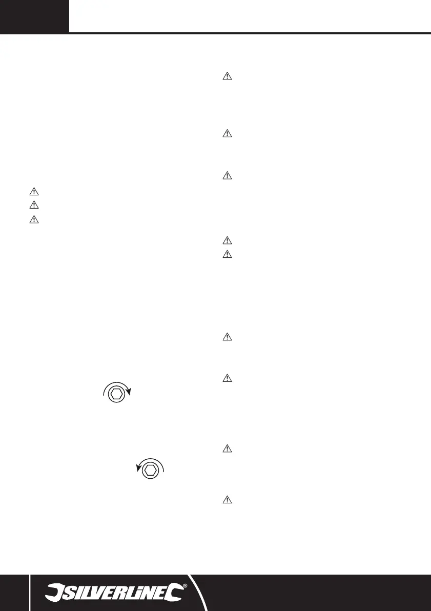
5. With Spindle Lock pressed use the 6mm Hex Key
(19) to remove the Arbor Bolt (40) by
turning the bolt clockwise (Image M):
6. Once the Arbor Bolt has been removed, carefully remove the spacers and the Blade (36) from the
cutter head
Replacing a blade:
1. After removing the existing Blade (36) (see steps 1–6 in ‘To remove a blade’ section of manual)
insert the Blade into the cutter head using any necessary spacers (Fig. II)
Note: Ensure the Blade is installed in the correct rotational directional.
2. Press and hold the Spindle Lock Button (9)
3. Using the 6mm Hex Key (19) tighten the
Arbor Bolt (40) by rotating the Bolt anticlockwise:
4. Release the Spindle Lock Button; ensure the Blade rotates freely and straight without wobbling
or sideways movement
5. ChecktheBladeis90°totheMitreTableusingasquare(ImageN)
6. Replace the Blade Guard mechanism screw and ensure the guard operates correctly before use
Note: After installing a Blade, always run the saw for a short time before use, to ensure the blade
is rotating and operating correctly. If there are any problems, immediately stop the saw, disconnect
from the mains power, and amend the problem.
Adjusting the mitre angle
The Mitre Lock (13) is used to lock the Mitre Table (42) at the desired mitre angle. The mitre saw cuts
from 0° to 45° both left and right.
WARNING: ALWAYS ensure the saw is disconnected from mains power before making any
adjustments to angles or bevels.
To adjust the mitre angle:
1. If locked, unscrew the Mitre Lock (13) anticlockwise
2. WiththeMitreLockreleased,rotatetheMitreTable(42)totherequiredmitreangleindicatedon
the Mitre Angle Gauge (17) via the Mitre Angle Indicator (16) (Image O)
3. Once positioned to the correct angle, tighten the Mitre Lock
WARNING: BEFORE MAKING ANY CUTS, ensure the Mitre Lock is always applied. Failure to
do so could result in the Mitre Table (42) moving during the cut and could cause serious personal
injury.
Adjusting the bevel angle
The saw blade can be set at a desired bevel angle to the left from 0° to 45°.
WARNING: ALWAYS ensure the saw is disconnected from mains power before making any
adjustments to angles, bevels, or plunge depths.
To adjust the bevel angle:
1. Ensure the Mitre Lock is locked
2. Turn the Bevel Locking Knob (29) anticlockwise to release the bevel lock
3. AdjustthebevelangleofthecuttertotherequiredangleusingtheBevelAngleGauge(22)for
reference (Image P)
4. WhentherequiredbevelangleisselectedtightentheBevelLockingKnobbyrotatingclockwise
WARNING: BEFORE MAKING ANY CUTS, ensure the Bevel Locking Knob is tight (29). Failure to
do so could result in the saw arm moving during the cut and could cause serious personal injury.
WARNING: ALWAYS ensure that the Sliding Fence (4) does not interfere with the Blades
cutting trajectory before making any cuts (see ‘Adjusting the Fence’ section in this manual.
Releasing & locking the slide rail locking knob
• The saw has a dual slide rail for adjusting the saw forwards and backwards across the cutting
table.
1. To allow sliding movement slacken the Slide Rails Locking Knob (30) (Image Q)
2. To lock the cutting head at a particular length tighten the Slide Rails Locking Knob
attherequiredlocation
Operation
WARNING:ALWAYSweareyeprotection,adequaterespiratoryandhearingprotection,and
suitable non-woven gloves when working with this tool.
IMPORTANT: Always inspect the mitre saw before each use. Before connecting the saw to mains
power, inspect the guards and the correct functioning safety features of the tool.
IMPORTANT:Ensuretheoperatorhasadequatetrainingintheoperation,adjustment,and
maintenance of the mitre saw before connecting the saw to mains power and operating the saw.
WARNING: ALWAYS ensure the tool is unplugged from mains power before adjusting or
changing any of the tool’s parts. Observe the rotational direction of the blade and compare to the
correct rotational direction on the saw blade; at the front of the saw, the blade teeth should always
point down.
Switching ON & OFF
• Toswitchthesaw‘ON’squeezetheON/OFFTriggerSwitch(24).
• Toswitchthesaw‘OFF’releasetheON/OFFTriggerSwitch.
Laser
WARNING: DO NOT look directly into the Laser as this can damage your eyes and potentially
cause blindness.
• The Laser operates independently of the saw
• ToswitchtheLaser(27)‘ON’press‘I’ontheLaserON/OFFSwitch(34)
• ToswitchtheLaser‘OFF’press‘0’ontheLaserON/OFFSwitch
Making a cut
WARNING: Never place hands closer than 150mm to the blade. Always keep hands and limbs
well clear from the path of the Blade (36) and the Blade Channel (6) (Fig III).
WARNING: Avoid hand positions and awkward usage operations where an accidental slip could
causeahandorngerstomoveintotheBlade.
IMPORTANT: For accurate cutting, ensure the blade, the fence, the mitre, and the bevels are all
calibrated correctly (see ‘Calibration’ in Maintenance).
546534_Manual.indd 12 28/09/2018 16:16