Smart Machine Smart Decision
SIM800_Hardware Design_V1.09 25 2016-06-30
At this moment, AT commands can not be executed any more, and only the RTC is still active. Power off mode
can also be indicated by STATUS pin, which is low level at this time.
4.2.3. Reset Function
SIM800 also have a RESET pin used to reset the module. This function is used as an emergency reset only when
AT command “AT+CPOWD=1” and the PWRKEY pin have no effect. User can pull the RESET pin to ground,
and then the module will restart.
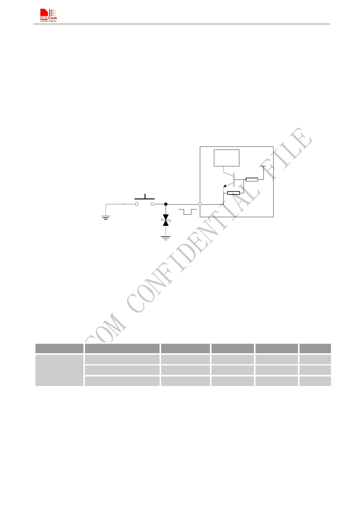
This pin is already isolated in the module, so the external isolation is not necessary. Following figure is internal
circuit of the RESET pin.
2.8V
RESET
Circuit
4.7K
RESET
Module
47K
Figure 14: Reset circuit
The typical value of RESET pin high level is 2.8V, so for the 3V or 3.3V, customer could use MCU’s GPIO to
driver this pin directly, resistor in serial the RESET signal could enhance the ESD performance but the value
should not be higher than 100Ω , otherwise the level of RESET could be lower than threshold value; RESET
hardware parameters can refer to the following table.
Table 6: Electronic characteristic of the RESET Pin
The reset scenarios are illustrated in the following figures.