Page 27
chutes on SPN 1205 model), has the function to stop
the operation of the ice machine when the light
beam between the light source and the receiver
gets interrupted by the flake ice which
accumulates in the chute.
When the light beam is interrupted the Bin Full
YELLOW LED located in the front of the P.C.
BOARD blinks; in case the light beam gets
interrupted for as long as 10 seconds, the ice
machine stops (drive motor keeps on working by
3' delay then stops) with the glowing-up of the
2nd YELLOW LED to monitor the full ice bin
situation. The 10 seconds of delay prevents that
any minimum interruption of the light beam due to
the regular ice chuting through the ice spout may
stop the operation of the unit.
NOTE. During the life of the machine the Ice
Level Control may require a recalibration
mainly when the glass of the two optical eyes
are covered by a thin lay of scale.
To do it just follow the following procedure:
• With unit OFF push and old the Reset
Button of the PC Board
• Give power to the machine through the
Green Master Switch
• Hold the PC Board Reset Button till the
leds start to blink/flash (more or less 10
seconds)
• Release the PC Board Reset Button
The Optical Ice Level Control is now
recalibrated.
Check for the correct operation of the Optical
Ice Level Control by plasing a handfull of ice
in between the two eyes.
The Bin Full yellow led must start to blink/
flash immediately and, 10 seconds later, the
machine must trip OFF.
As soon as the ice is scooped out (with the
resumption of the light beam between the two
infrared sensor of ice level control) 10 seconds
later the ice machine resumes its operation with
the simul-taneous extinguishing the 2nd YELLOW
LED.
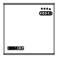
F. P.C. BOARD (Data processor)
The P.C. BOARD, fitted in its plastic box located
in the front of the unit, consists of two separated
printed circuits one at high and the other at low
voltage and protected by fuses. Also it consists of
five aligned LEDS monitoring the operation of the
machine of three jumpers (TEST used only in the
factory, 60/70°C used to set up the PC Board at
proper safety cut out condensing temperature and
3' to by pass the 3 minutes Stand By) and of input
terminals for the leads of the sensor probes as
well as input and output terminals for the leads of
the ice maker electrical wires.
The P.C. BOARD is the brain of the system and
it elaborates, through its micro processor, the
signals received from the sensors in order to
control the operation of the different electrical
components of the ice maker (compressor, gear
motor, etc.).
The five LEDS, placed in a row in the front of the
P.C. BOARD, monitor the following situations:
GREEN LED
Unit under electrical
power
YELLOW LED
- Blinking: I/R beam cut
out
- Steady: unit shut-off at
storage bin full
- Blinking fast: I/R beam resumed
YELLOW LED
Unit shut-off due to a
too lo-water level into
float tank
RED LED
ON all the time
- Unit shut-off due to a too
hi-condensing temperature
- Unit shut-off due to a too
lo-ambient temperature <+1°C
Blinking
3 minutes start up delay time
YELLOW LED
ON all the time
- Unit shut-off due to the wrong
rotation direction of gear motor
- Unit shut-off due to the
too lo speed of gear motor
Blinking
- Unit shut-off due to a
too hi-evaporating temp.
>-1°C after 10 min of operation
YELLOW AND
RED LED
- Blinking: Evaporator sensor
out of order
- Steady: Condenser sensor
out of order
- Blinking alternatively: Ice level
control out of order