22
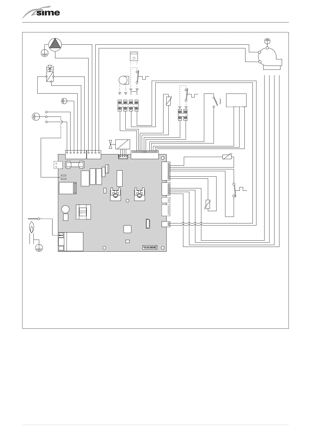
5.11 Wiring diagram
BLACK
BLUE
BROWN
TRA
EV
F
CN11
BLUE
BLUE
BLACK
BLACK
TA1
SE
3 4 5 6
BROWN
BLUE
PI
VD
2 3
1
BLUE
BROWN
L
N
CN6
CN5
CN3
CN17
CN4 CN1
CN15
CN14
CN13CN12
CN2
RED
RED
RED
GREEN
WHITE
RED
RED
RED
RED
SS
PA
V
FLM
SF
TS
SM
VCC
GND
IN
BLACK
BLACK
BLUE
RED
GREEN
BLACK
BLUE
BLUE
4 3 2 1
BLUE
BLACK
GREEN
RED
BLUE
BROWN
EAR
CR
BLACK
BLACK
TA2
L
Live
N
Neutral
F
Fuse (3.15AT) (3.15AT - 250V)
TRA
Ignition transformer
PI
Pump
V
Fan
EAR
Ignition / Detection electrode
EV
Gas solenoid valve
SS
Domestic hot water sensor (SS)
SM
Delivery sensor (SM)
TS
Safety thermostat
SF
Exhaust sensor (SF)
FLM
Flow meter
VD
Diverter valve
PA
Water pressure switch
TA1-TA2
Room Thermostat
SE
External sensor
CR
Sime EASY HOME or HOME or HOME
PLUS remote control (alternative to TA1)
To connect the "TA" remove the jumper between terminals 5-6.
Fig. 15
m
CAUTION
Installer must:
– Connect the boiler to a 230v -50Hz single phase
power supply through a fused mains switch, with
at least 3mm spacing between contacts, fused at
3amps
which ensures complete cut-off in overvoltage
category III conditions (i.e. where there is at least 3
mm between the open contacts)
.
– Respect the connections L (Live) - N (Neutral).
– Ensure that the special power cable is only re-
placed with a cable ordered as a spare part and
connected by professionally qualified personnel.
m
CAUTION
Installer must:
– Connect the earth wire to an effective earthing
system.
Sime Ltd declines all responsible for any in-
jury or damage to persons, animals,or property as a
result of f
ailure to provide adequate earthing of the
appliance
.
d
DO NOT
Do not use water pipes for earthing the appliance.
 Loading...