30
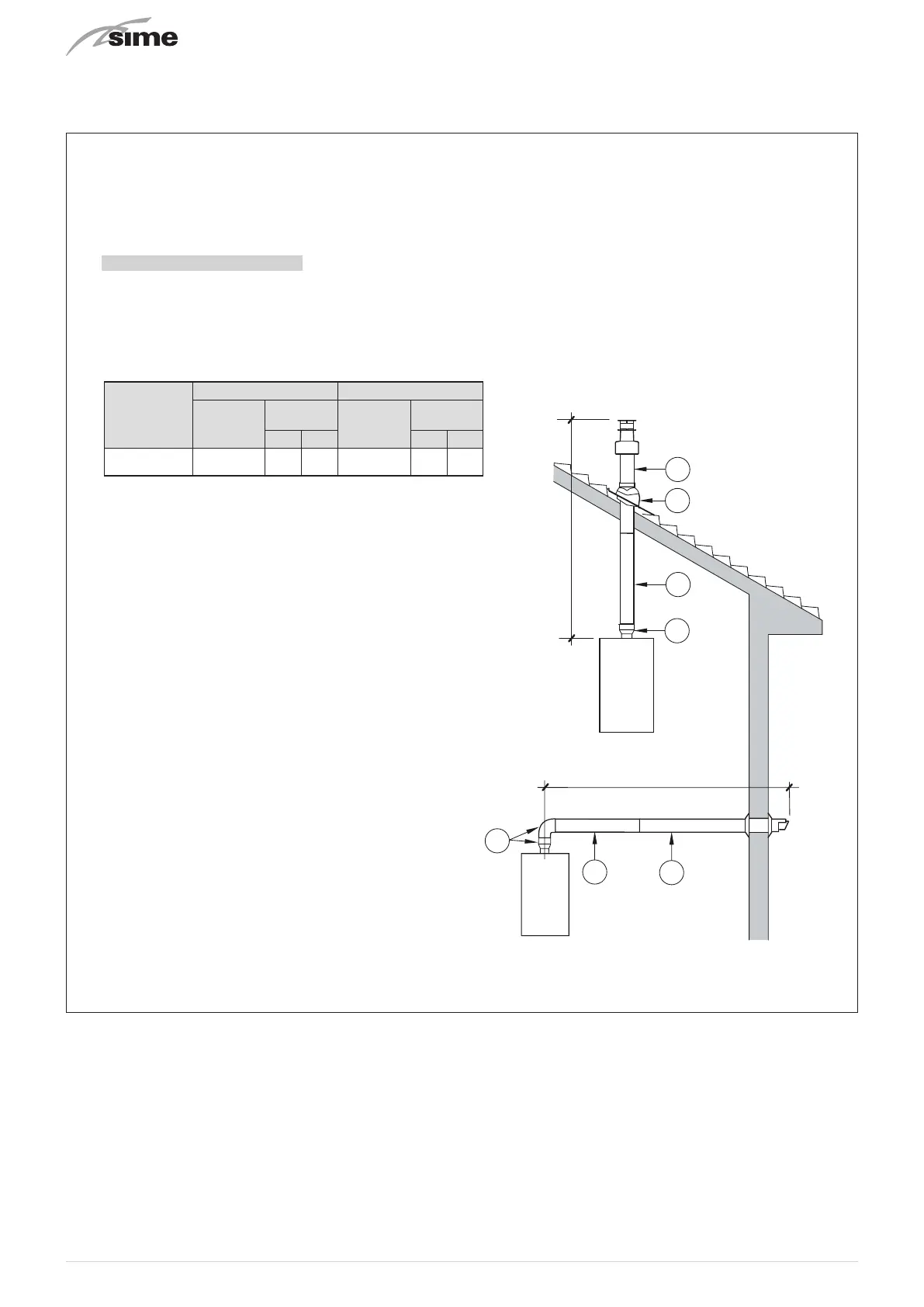
6.12.2 Installation of coaxial flues 60/100mm – 80/125mm
Coaxial flue kits that are supplied separately. The diagrams below, illustrate some examples of fluing options allowed and the
maximum lengths than can be achieved. It is essential that a flue gas analysis point is made available directly above the boiler.
C33
6
5
3
2
C43
3
4
2
x
y
x + y = L (m)
H (m)
C13
1
2
1
L (m)
2
H (Horizontal) m
– The insertion of each additional 90° bend with a diameter of 60/100 (code 8095850) reduces the available section by 1.5 meters.
– The insertion of each additional 90° bend with a diameter of 80/125 (code 8095870) reduces the available section by 2 meters.
– Each additional 45° curve installed a diameter of 60/100 (code 8095950) reduces the available length by 1.0 metres.
– Each additional 45° curve installed a diameter of 80/125 (code 8095970) reduces the available length by 1.0 metres.
HORIZONTAL FLUES MUST BE LEVEL
NOTE: Before connecting accessories, it is always advisable to lubricate the
internal part of the gaskets with silicon products. Avoid using oils and greases.
V (Vertical) m
ACCESSORIES
a Coaxial duct kit L. 790 code 8096250
b Telescopic coaxial duct kit L. 695 code 8098605
a Extension L. 1000 code 8096150
b Extension L. 500 code 8096151
Vertical extension L. 140 with coupling code 8086950
Tile for joint code 8091300
Terminal for roof exit L. 1285 code 8091212 (includes 8086950)
ACCESSORIES
Coaxial duct kit L. 785 code 8096253
a Extension L. 1000 code 8096171
b Extension L. 500 code 8096170
Adapter for ø 80/125 code 8093150
Tile for joint code 8091300
Terminal for roof exit L. 1285 code 8091212 (includes 8086950)
Model
Length of pipe Ø 60/100 Length of pipe Ø 80/125
H
(m)
V
(m)
H
(m)
V
(m)
Min.
Max.
Min.
Max.
6 1,3 7 10 1,2 13
MIA-30
Fig. 23
 Loading...