17
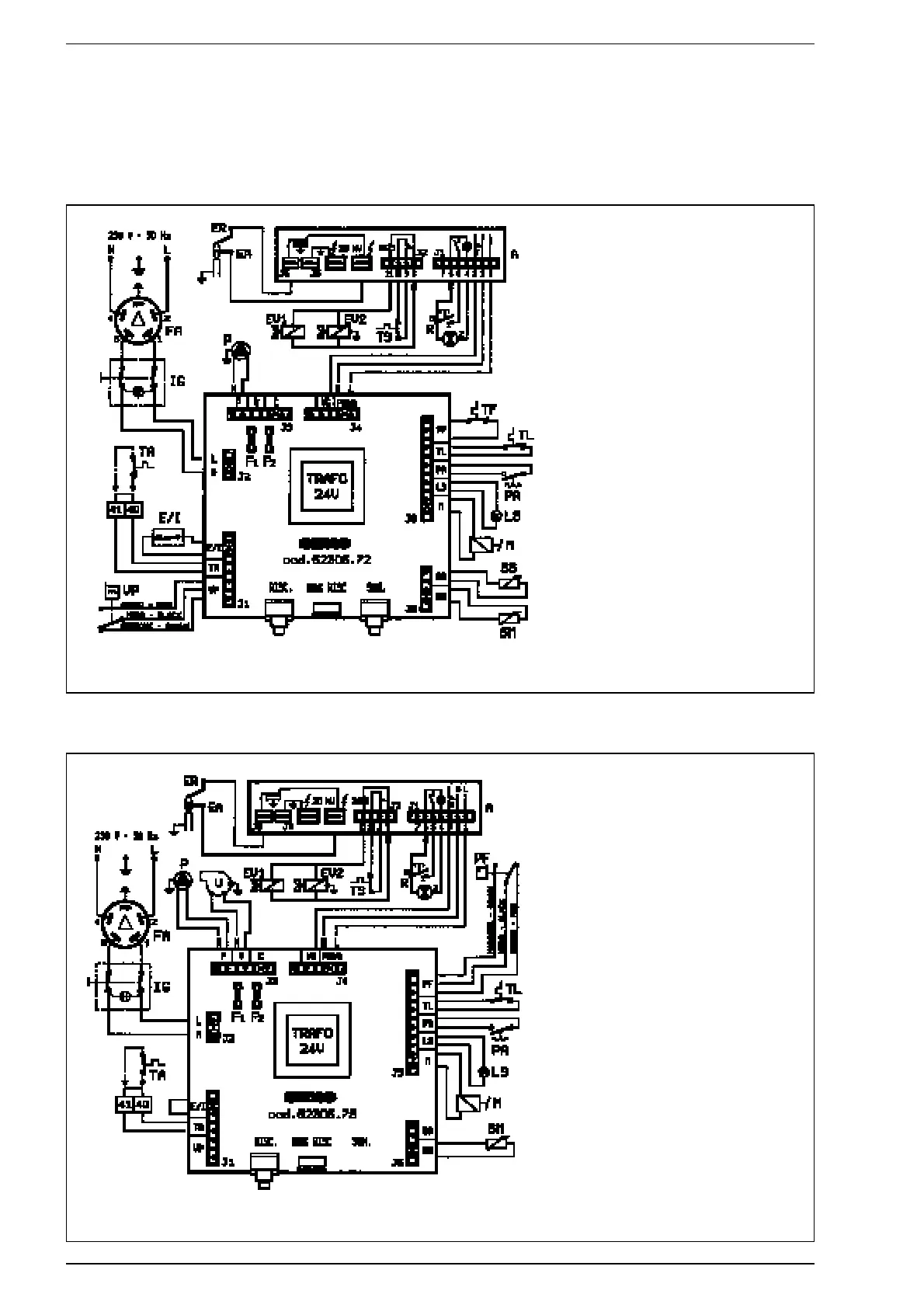
KEY
LLine
N Neutral
IG Main switch
E/I Summer/Winter switch
TA Room stat
SS D.H.W. sensor (red)
SM Heating flow sensor (blue)
F1 Fuse (T1,6A)
F2 Fuse (F 50 mA)
A FM 11 programmer
EA Ignition electrode (orange)
ER Sensing electrode (white)
EV1 Gas valve coil
EV2 Gas valve coil
TS 100°C safety stat
R Equipment lock out reset button
TL 85°C limit stat
M Modulator
VP Pressure switch valve
P Circulation pump
TF Smoke stat
PA Water pressure switch
LS Insuff. water pressure warning lamp
FA EMC filter
KEY
LLine
N Neutral
SM Heating flow sensor (blue)
LS Insuff. water pressure warning lamp
PA Water pressure switch
IG Main switch
F1 Fuse (T 1.6A)
F2 Fuse (T 50mA)
TA Room stat
P Circulation pump
A FM11 programmer
EA Ignition electrode (orange)
ER Sensing electrode (white)
EV1 Gas valve coil
EV2 Gas valve coil
TS 100°C safety stat
R Equipment lock out reset
PF Smoke pressure switch
V Fan
TL 85°C limit stat
M Modulator
FA EMC filter
NOTE: The room stat must be connected to the terminals 40-41 of the
three-pole terminal strip after removing the link.
NOTE: The room stat must be connected to the terminals 40-41 of the
three-pole terminal strip after removing the link.
2.12.4 “MURELLE 20 CE IONO - 25 CE IONO” wiring diagram
2.12.5 “MURELLE 20 BFR CE IONO” wiring diagram
Fig. 21
Fig. 22