18
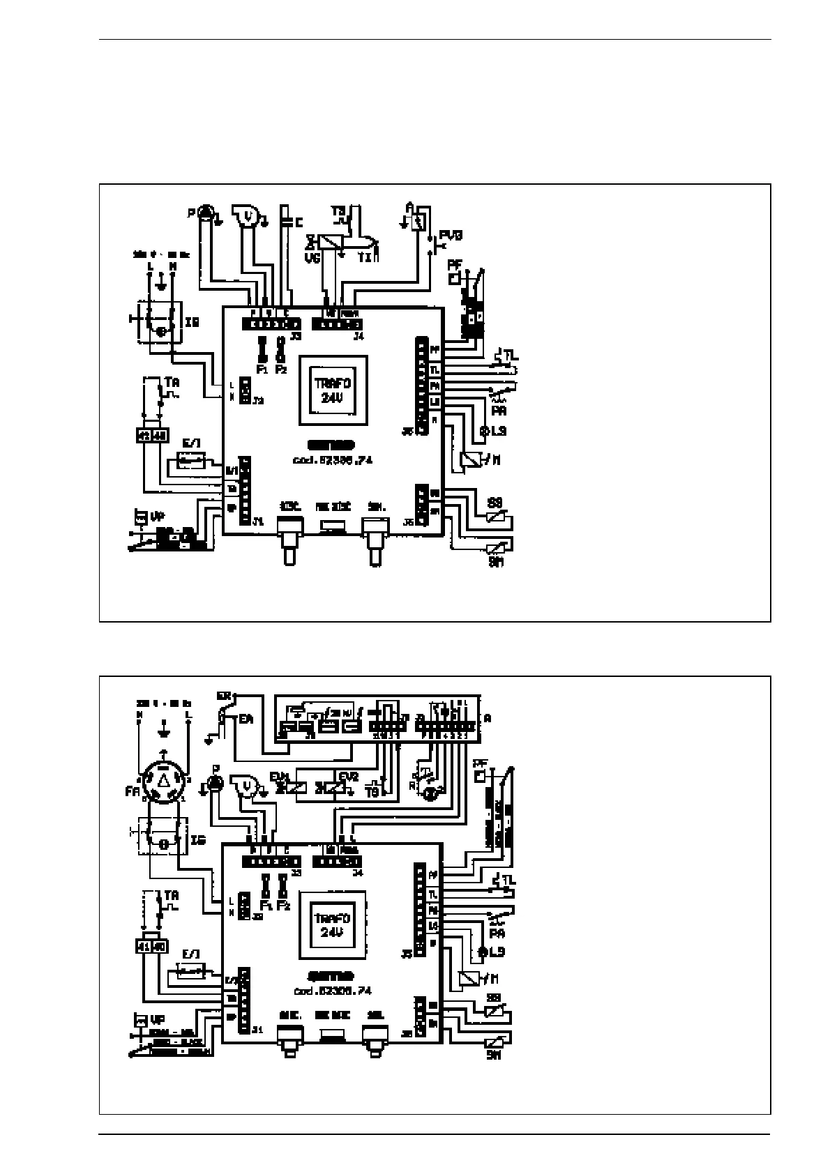
KEY
L Line
N Neutral
SS D.H.W. sensor (red)
SM Heating flow sensor (blue)
LS Insuff. water pressure warning lamp
PA Water pressure switch
IG Main switch
F1 Fuse (T 1.6A)
F2 Fuse (F 50mA)
TA Room stat
E/I Summer /Winter switch
VP Pressure switch valve
P Circulation pump
PVG Gas valve microswitch
A Electric ignition
PF Smoke pressure switch
C Fan capacitor
V Fan
TL 85°C limit stat
VG Gas valve
TS 100°C safety stat
TI Interrupted thermocouple
M Modulator
KEY
L Line
N Neutral
SS D.H.W. sensor (red)
SM Heating flow sensor (blue)
LS Insuff. water pressure warning lamp
PA Water pressure switch
IG Main switch
F1 Fuse (T1,6A)
F2 Fuse (F 50 mA)
TA Room stat
E/I Summer/Winter switch
VP Pressure switch valve
P Circulation pump
A FM11 programmer
EA Ignition electrode (orange)
ER Sensing electrode (white)
EV1 Gas valve coil
EV2 Gas valve coil
R Equipment lock out reset button
PF Smoke pressure switch
V Fan
TL 85°C limit stat
TS 100°C safety stat
M Modulator
FA EMC filter
NOTE: The room stat must be connected to the terminals 40-41 of the
three-pole terminal strip after removing the link.
NOTE: The room stat must be connected to the terminals 40-41 of the
three-pole terminal strip after removing the link.
2.12.6 “MURELLE 20 BF CE” wiring diagram
2.12.7 “MURELLE 20 TX CE IONO - MURELLE 20/25 BF CE IONO” wiring diagram
Fig. 23
Fig. 24