98
3.2
T
EMPERATURE SENSORS
AND WATER PRESSURE
TRANSDUCER
Tables 3 - 3/a show the resistance values
(Ω) that are obtained on the sensors as the
temperature varies and the transducer
when the pressure varies.
With the C.H. sensor (SM) interrupted
the boiler will not function with both
services.
With the D.H.W. sensor (SB) interrupted
the boiler functions only with heating.
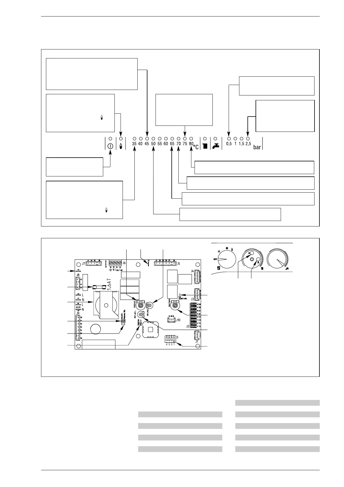
Green led off
in case of no electricity
Red led flashing: in case of
insufficient water pressure (*)
Red led flashing: problem with C.H. sensor (SM)
Red led flashing: coil of the modulator stopped
Red led flashing: problem in flame detector circuit
Red led flashing:
in case of C.H. safety valve
interception (*)
Red led flashing: lack
of communication with the
“Logica Remote Control”
Red led on: ignition failure.
Turn the selector
CR/OFF/EST/INV/UNBLOCK
in the position unblock ( )
to restore functioning
Red led flashing: safety stat
interception. To restore
functioning turn the selector
CR/OFF/EST/INVE/UNBLOCK
in the position unblock ( )
Red led flashing: fan fault.
After 30 minutes of the switching
off of the fan the panel will reactivate it.
(*)
When all the leds from 0,5 to 2,5 bar are switched off check
the connections of the water pressure transducer.
Fig. 20
Red led flashing: smoke pressure switch fault.
KEY
1 Ignition electrode earth faston,
3 Fuse (1.6 AT)
5 Connector “ANN. RIT.”
6 Trimmer “POT. ACC.”
7 Connector “MET-GPL”
8 D.H.W. potentiometer
9 Detection electrode faston
10 Trimmer “POT. RISC.”
11 C.H. potentiometer
12 Selector CR/OFF/EST/INV/UNBLOCK
13 DIP SWITCH
14 Connector “Modureg Sel.”
15 Connector “Albatros”
Fig. 21
NOTE: In order to have access to the regulating trimmer, (6) and (10), take out
the C.H. potentiometer knob.
TABLE 3 (Sensors)
Temperature (°C) Resistance (Ω)
20 12.090
30 8.313
40 5.828
50 4.161
60 3.021
70 2.229
80 1.669
TABLE 3/a (Transducer)
Pressure Resistance (Ω)
(bar) min max
0 297 320
0,5 260 269
1 222 228
1,5 195 200
2167173
2,5 137 143
3108113
3,5 90 94



 To Next Page