3.3 ELECTRONIC IGNITION
The ignition and flame sensing are control-
led by two electrodes that guarantee the
maximum safety, with a time of intervention
of one second for accidental switching off or
lack of gas.
3.3.1 Functioning cycle
Turn the selector knob to summer or winter
and note, from the lighting up of the green
led ( ), whether electricity is present.
The starting up of the burner should take
place within a maximum of 10 seconds.
We can summarise the manifestations of a
failure to start, with consequent activation
of the failure signal as follows:
– Gas failure
The ignition electrode continues to spark
for a maximum of 10 seconds, the pilot
burner does not start, the blockage indi-
cator lights up.
This may occur at the first ignition
attempt or after long periods of inactivity
with the presence of air in the tubing.
May be due to the gas cock being closed
or a break in the valve coil, which do not
allow opening.
– The ignition electrode does not give a
jump spark
In the boiler only the gas opening to the
burner is noted, after 10 seconds the
block signal lights up.
May be due to the fact that the cable of
the electrode is interrupted or is not well
fixed to the terminal of the ignition tran-
sformer.
– The flame is not detected
From the time of the ignition a continuous
jump spark from the electrode is noted
despite the burner being lit. After 10
seconds the sparking stops, the burner
goes off and the block signal lights up.
The cable of the detector electrode is
interrupted or the electrode itself is
earthed; the electrode is very worn and
needs to be replaced. The control board
is faulty.
Due to a sudden fall in electricity the burner is
immediately arrested, once the electricity is
restored, the boiler will automatically restart.
3.4 SMOKE PRESSURE SWITCH
The switch with a fixed setting 6.0-7.5 mm
H
2
O (vers. “25/60”) and 3.5-4.5 mm H
2
O
(vers. “30/60”), is able to guarantee the
functioning of the boiler with inlet and outlet
pipes at the maximum limit length allowed.
The value of the smoke pressure switch
signal is measured with a special instru-
ment connected to the positive and negati-
ve pressure plugs on the upper part of the
sealed chamber.
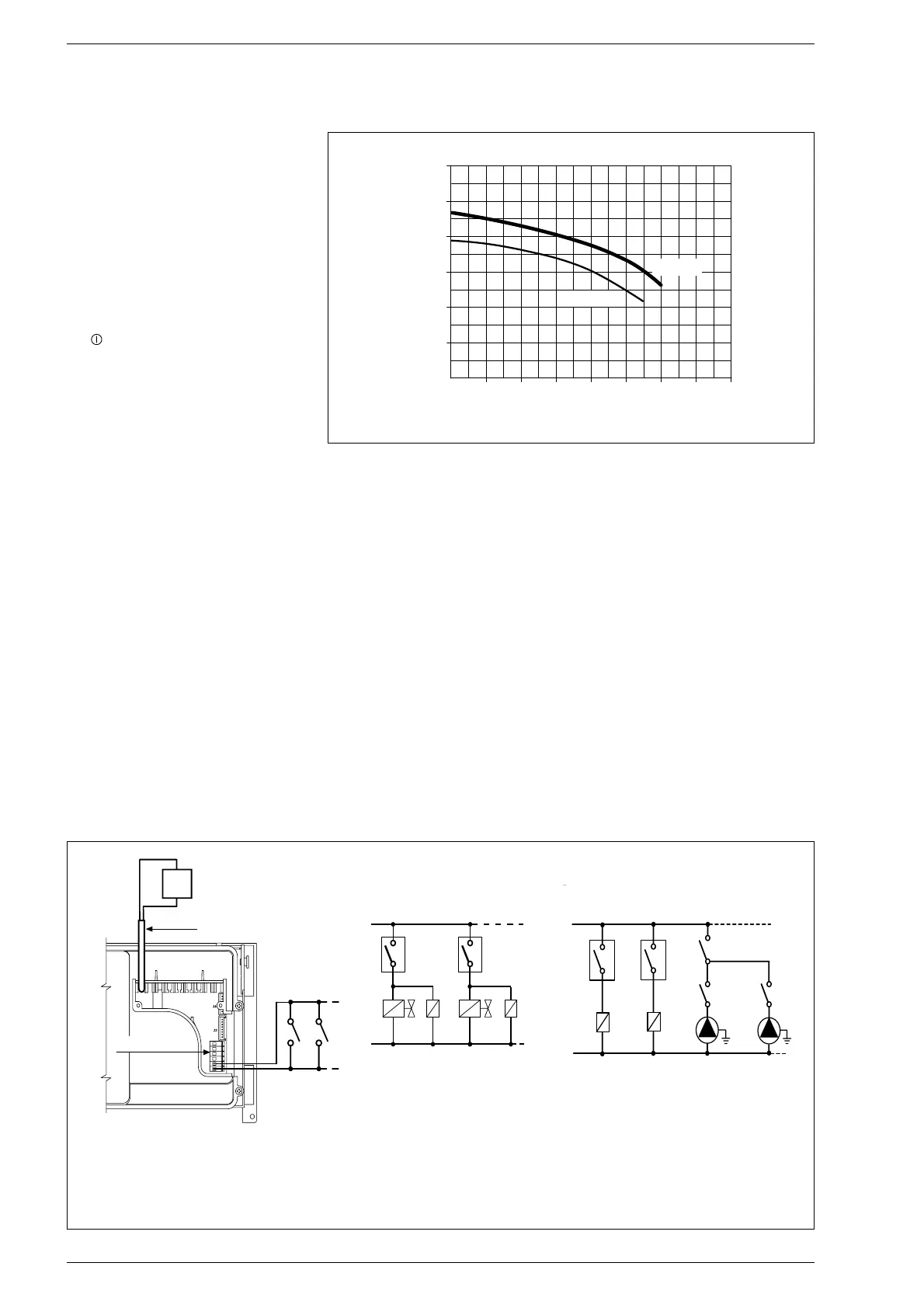
3.5 SYSTEM AVAILABLE HEAD
The residual head for the heating plant is
represented, in function of the C.H. flow, by
the graph in fig. 22.
3.6
MAINS ELECTRICITY CONNECTION
Use a separate electric line to link up the
room stats and relative zone valves or
pumps. The connection of the micros or
the relay contacts is carried out on the
connector of control board (J2) after
having removed the existing bridge (fig. 23).
99


 To Next Page
 Loading...