100
4.1 D.H.W. PRODUCTION
The preparation of hot water is guaranteed
by the glass enamelled tank unit with
magnesium anode for the protection of the
tank and inspection flange for its control
and cleaning.
The magnesium anode must be checked
annually and substituted when it is worn.
If the boiler does not produce hot water,
make sure that the air has been released
by pressing on the manual vents after
having switched off the main switch.
4.2 GAS VALVE
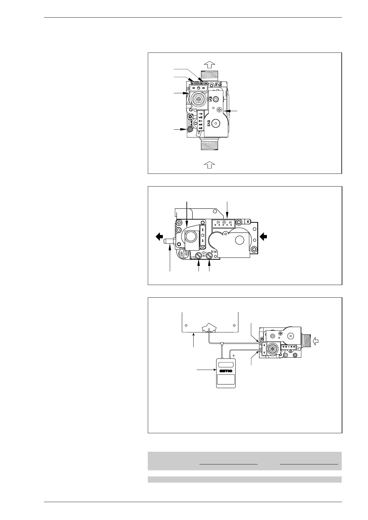
The boiler is produced with SIT 845 SIGMA
gas valve (fig. 24) and HONEYWELL VK
8105N gas valve (fig. 24/a).
NOTE: In case of replacement of the SIT
gas valve to HONEYWELL or vice-versa,
press on the “Modureg” connector of
electronic panel (14 fig. 21). With the
bridge disconnected the boiler is predi-
sposed to function with the SIT gas valve,
and with the bridge connected it is predi-
sposed to function with the HONEYWELL
gas valve.
The gas valve is set at two pressure values:
maximum and minimum, that correspond,
according to the type of gas, to the values
indicated in Table 4.
The setting of the gas pressure at mini-
mum and maximum values is carried out by
SIME: variations are discouraged.
Only in the passing from one type of gas
supply (methane) to another (butane or
propane) is a change in the working pressu-
re allowed.
It is essential that this operation is car-
ried out by authorised personnel.
Once the change in working pressure has
been carried out, seal the regulators.
When proceeding with the setting of the
pressure, it is necessary to follow a pre-
established order, first the MAXIMUM and
then the MINIMUM.
4.2.1 Maximum and minimum pressure
adjustment SIT 845 SIGMA
In order to carry out the setting of the
maximum pressure proceed in the fol-
lowing way (fig. 25):
– Connect the differential manometer as
shown in fig. 24/b.
– Remove the plastic cap of the modulator
(1).
– Place the D.H.W. potentiometer knob on
the maximum value.
– Start the boiler by pressing the rotary
switch and open the hot water cock.
– Using a 10 wrench turn the nut (3) to
find the maximum pressure as shown in
Table 4: to reduce the pressure turn the
nut anti-clockwise, to increase the pres-
sure turn the nut clockwise.
4 USE AND MAINTENANCE
Fig. 24
KEY
1 Modulator
2 EV1-EV2 coils
3 Pressure inlet upstream
4 Pressure inlet downstream
5 VENT plug
TABLE 4
Burner max. Modulator Burner min. Modulator
Gas type pressure current pressure current
mbar mA mbar mA
Methane (G20) 10,8 - 11,3 130 1,9 - 1,7 0
Butane (G30) 28,4 - 28,1 165 4,7 0
Propane (G31) 35,3 - 35,9 165 4,7 0


 To Next Page
 Loading...