90
2.7.4 Roof outlet coaxial duct
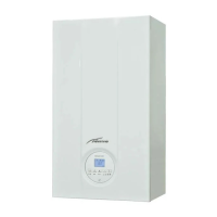
The roof outlet terminal L.1284 cannot be
shortened and the positioning of the tile
distances must be no less than 600 mm
from the discharge terminal outlet (fig.
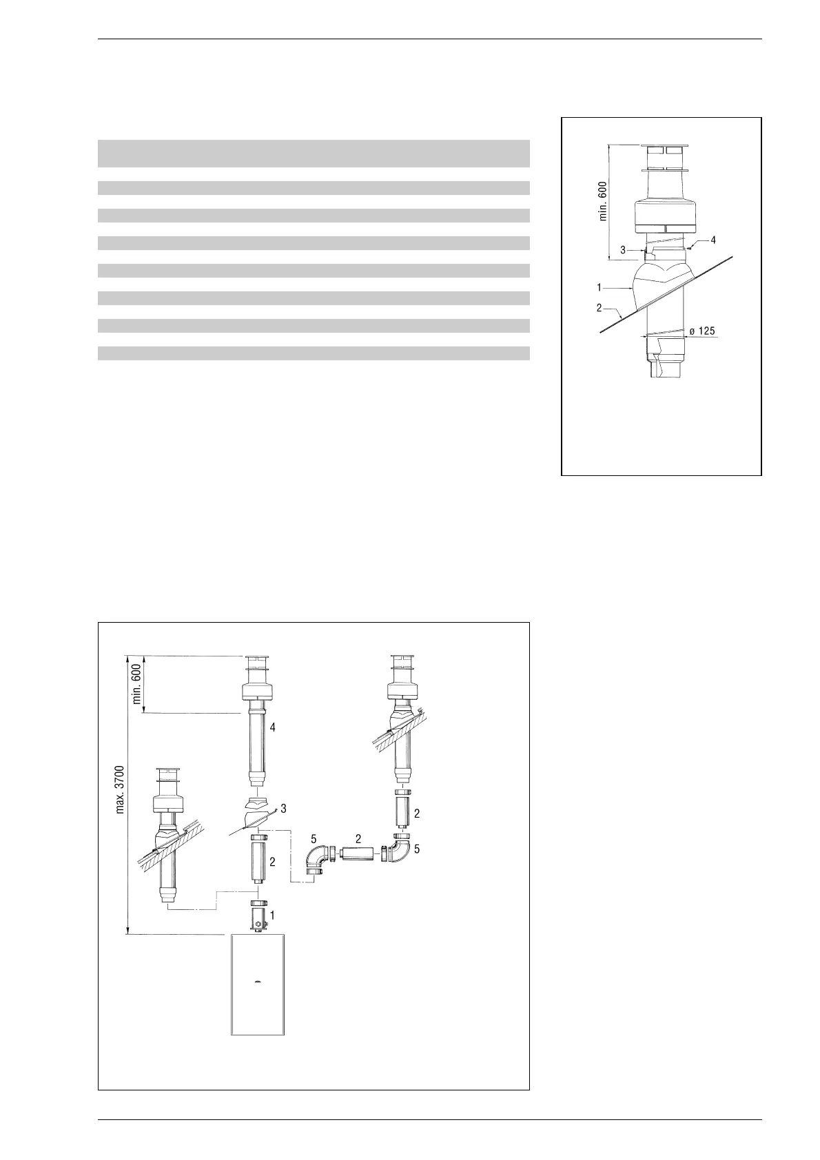
11). The accessories required for this
type of installation and some of the con-
necting systems that can be used are
shown in fig. 12.
Up to a maximum of
three extensions can be added to reach a
rectilinear length of 3.7 metres.
2.8 SEPARATE DUCTS
In the installation it is best to observe the
directions requested by the Norms and a
few practical considerations:
– With direct external suction, when the
duct is greater than 1 m in length, insu-
lation is recommended in order to avoid,
in particularly cold periods, the formation
of dew on the outside of the tubing.
– With discharge duct positioned on the
outside of the building, or in cold environ-
ments, insulation is necessary to avoid
starting failures of the burner. In such
cases, a system for the collection of con-
densation must organised.
–
If a segment of the flue passes through
a flammable wall, this segment must be
insulated with a glass wool pipe insula-
tor 30 mm thick, with a density of 50
kg/m
3
.
The maximum total length obtained by
summing up the lengths of the suction
and discharge tubing is determined by
the load losses of the single fittings atta-
ched (excluding the splitter) and must not
be greater than 8.00 mm H20 (vers.
“25/60”) and 9.00 mm H2O (vers.
“30/60 ”).
For the load losses of the fittings refer to
Table 2.
2.8.1 Separate ducts
accessories
For the realisation of this type of discharge
is supplied a kit cod. 8093000 (fig. 13).
The sector diaphragm in the kit, must be
used according to the maximum load loss
allowed in both ducts, as indicated in fig.
TABLE 1
1) Terminals below a practicable balcony must be located in such a way that the total path of the
smoke from its outlet point from the terminal to its outlet point from the external perimeter of
the balcony, including the height of possible railings, is not less than 2000 mm.
2) When siting terminals, where materials that may be subject to the action of the combustion pro-
ducts are present in the vicinity, e.g., eaves, gutters and downspouts painted or made of plastic
material, projecting timberwork, etc., distances of not less than 1500 mm must be adopted,
unless adequate shielding is provided to guard these materials.
Siting of terminal Appliances from 7 to 35 kW
(distances in mm)
A - below openable window 600
B - below ventilation opening 600
C - below eaves 300
D - below balcony (1) 300
E - from adjacent window 400
F - from adjacent ventilation opening 600
G - from horizontal or vertical soil or drain pipes (2) 300
H - from corner of building 300
I - from recess in building 300
L - from ground level or other treadable surface 2500
M - between two terminals set vertically 1500
N - between two terminals set horizontally 1000
O - from a surface facing without openings or terminals 2000
P - as above but with openings and terminals 3000
KEY
1 Tile with articulated joint
2 Lead panel
3 Collar
4 Locking screw
Fig. 11
Fig. 12
KEY
1 Vertical extension L. 194
with take-off points code 8086903
2 Extension L. 815 code 8084804
3 Tile with articulated joint code 8091300
4 Roof outlet terminal L. 1284
code 8091200
5 Supplementary 90° elbow code 8085601
 Loading...