The connectors are polarised in such a
way that the order cannot be inverted.
To install the control system these con-
nectors must be connected and
jumpers 4-5 and 11-12 must be
removed from the terminal board
(marked in bold in fig. 6).
The control sustem allows for the use
of sensors and environment units
whose connectors, polarised and
coloured, are found in a bag inside the
control board.
50
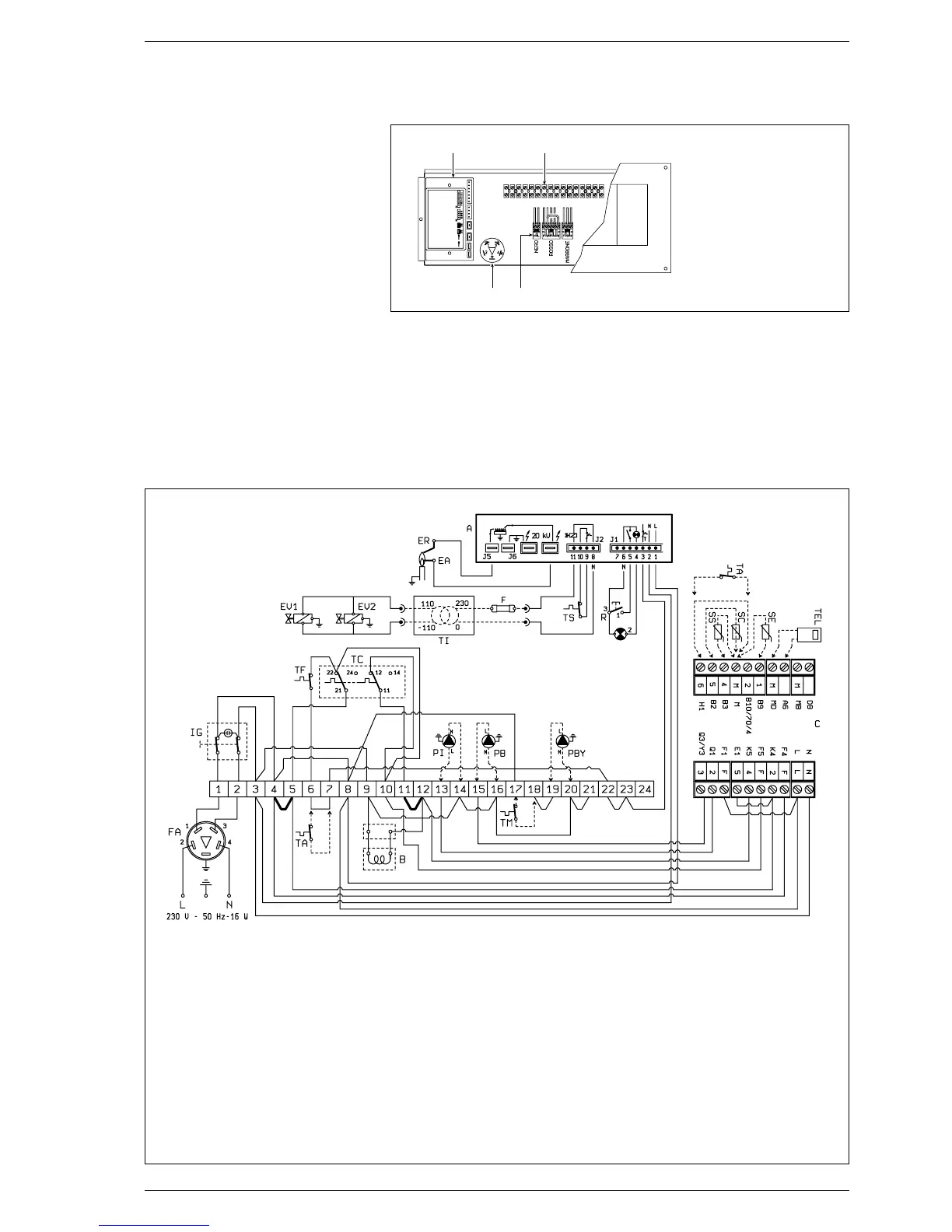
KEY
IG Main switch
TC Regulation stat with double contact
EA Ignition electrode
EV2 Gas valve coil
EV1 Gas valve coil
TA Room stat
R Lock out reset button
B Coil assembly
ER Sensing electrode
TS Safety stat
A FM 11 control box
TF Smoke stat
Fig. 6
2.6.2 Wiring diagram
FA EMC filter
PI C.H. pump
PB D.H.W. pump
TEL Environment unit QAA70
type (optional)
SE External temperarure
sensor (option)
SC Boiler immersion sensor
QAZ21 type (optional)
SS D.H.W. tank immersion
sensor QAZ21 type (optional)
C Control system connectors
(black - red - brown)
F Fuse (T 200mA)
TI Isolated transformer
(only for FR/BE)
PBY By-pass pump
TM Minimum temperature stat
NOTE: When connecting the room
stat remove the jumpers between
terminals 6-7. When connecting the
control system remove jumpers 4-5
and 11-12.
1 2
3 4
Fig. 5
KEY
1
EMC filter
2
Control system
connectors
(black- red- brown)
3
FM 11 control box
4
Terminal board
 Loading...