53
4.1 GAS VALVE
“RMG Mk.II” boilers come equipped
standard with a HONEYWELL VR
4605 C gas valve (for “70 - 80”
models) and VR 4605 CB gas valve
(for “90 - 100” models).
When the boiler is ignited the first
time, it is always recommended to
bleed the piping by using the pressu-
re outlet upstream from the valve
(fig. 10).
4.2 GAS VALVE ADJUSTMENT
T
he “RMG Mk.II” boilers have the gas
valve equipped with a coil assembly,
which enables, via the double-contact
regulating thermostat, a reduction in
output corresponding to approx. 60%
of nominal output before the burner
goes out completely. Calibration of the
operating pressures is done by SIME in
the factory. Consequently they should
not be altered. Only when you switch to
another type of gas (butane or propa-
ne) is it permitted to alter the opera-
ting pressures (Table 1).
It is essential that this operation be
carried out exclusively by authorized
technical staff. When the working
pressures have been adjusted, reseal
the regulators.
When the gas pressures are to be
reset, this must be done following a set
order: first the maximum pressure and
then the minimum.
4.2.1 Nominal pressure
adjustment
To set the maximum pressure, pro-
ceed as follows (fig. 11):
– connect the pressure column or a
pressure gauge to the pressure
intake located on the burner
manifold;
– unscrew the screw (4) completely;
– set the knob of the thermostat to
the maximum value;
– supply electric power to the boiler;
– loosen the locknut (1) and turn the
connection (3):
to reduce the pressure, turn the
connection counterclockwise; to
increase the pressure, turn the con-
nection clockwise;
– tighten the locknut (1);
– operate the main switch a number
of times, making sure that the maxi-
mum pressure corresponds to the
values given in Table 1.
4.2.2 Reduced pressure
adjustment
To set the reduced pressure, proceed
as follows (fig. 11):
–
deactivate the coil (2) electric supply;
– switch on the boiler and after a
short period of operation at nominal
output, turn the thermostat knob
slowly towards the minimum posi-
tion until you hear the click of the
first contact of the thermostat;
– leave the knob in that position and,
turning the screw (4), seek the mini-
mum pressure value according to
Table 1 for the gas in question: to
reduce the pressure, turn the
screw counterclockwise; to increase
the pressure, turn the screw
clockwise;
– restore electric power to the coil;
– operate the main switch a number
of times, making sure that the mini-
mum pressure corresponds to the
value given in Table 1.
4.3 GAS CONVERSION
To convert to butane gas (G30) or pro-
pane gas (G31), the main nozzles must
be replaced with another supplied in
the boiler gas conversion kit and apply
4 USE AND MAINTENANCE
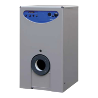
KEY
1 EV1 coil
2 Pressure regulator
3 Coil assembly
4 EV2 coil
5 LPG adaptor
6 Plastic cap
7 Pressure inlet upstream
8 Pressure inlet
downstream
Fig. 10
70 Mk.II 80 Mk.II 90 Mk.II 100 Mk.II
Methane - G20
Burner max. pressure mbar 9.3 9.1 9.3 9.3
Burner min. pressure mbar 4.5 4.6 4.7 4.7
Butane - G30
Burner max. pressure mbar 25.2 25.4 25.1 25.1
Burner min. pressure mbar 12.2 12.3 12.0 12.5
Propane - G31
Burner max. pressure mbar 32.6 30.2 30.0 32.7
Burner min. pressure mbar 16.4 16.1 15.6 16.6
TABLE 1
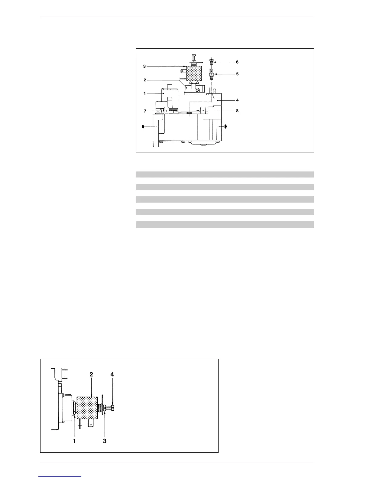
LEYENDA
1 Locknut M13
2 Coil
3 Max. press. adjust. connection
4 Min. pressure adjust. screw
Fig. 11
 Loading...