2.8 ø 80 SEPARATE PIPES
INSTALLATION
When installing the pipes, follow closely the
requirements of the current standards, as
well as the following practical indications:
– With direct intake from outside, when
the pipe is longer than 1 m, you are rec-
ommended to insulate the piping so as
to prevent formation of dew on the out-
side of the piping during certain periods
of the year.
–
With the outlet pipe outside the building or
in cold indoor environments, insulation is
necessary to prevent burner failure while
starting. In such cases, provide for a con-
densate-collector system on the piping.
–
If a segment of the flue passes through a
flammable wall, this segment must be
insulated with a 30 mm thick glass wool
pipe insulator, with a density of 50 kg/m
3
.
The maximum overall length of the intake
and exhaust ducts depends on the head
losses of the single fittings installed and
must not exceed than 6,00 mm H
2
O.
During installation use only original SIME
accessories and make sure that the con-
nection is carried out properly, as indicated
in the accessory instructions.
For head losses in the fittings, refer to
Table 1.
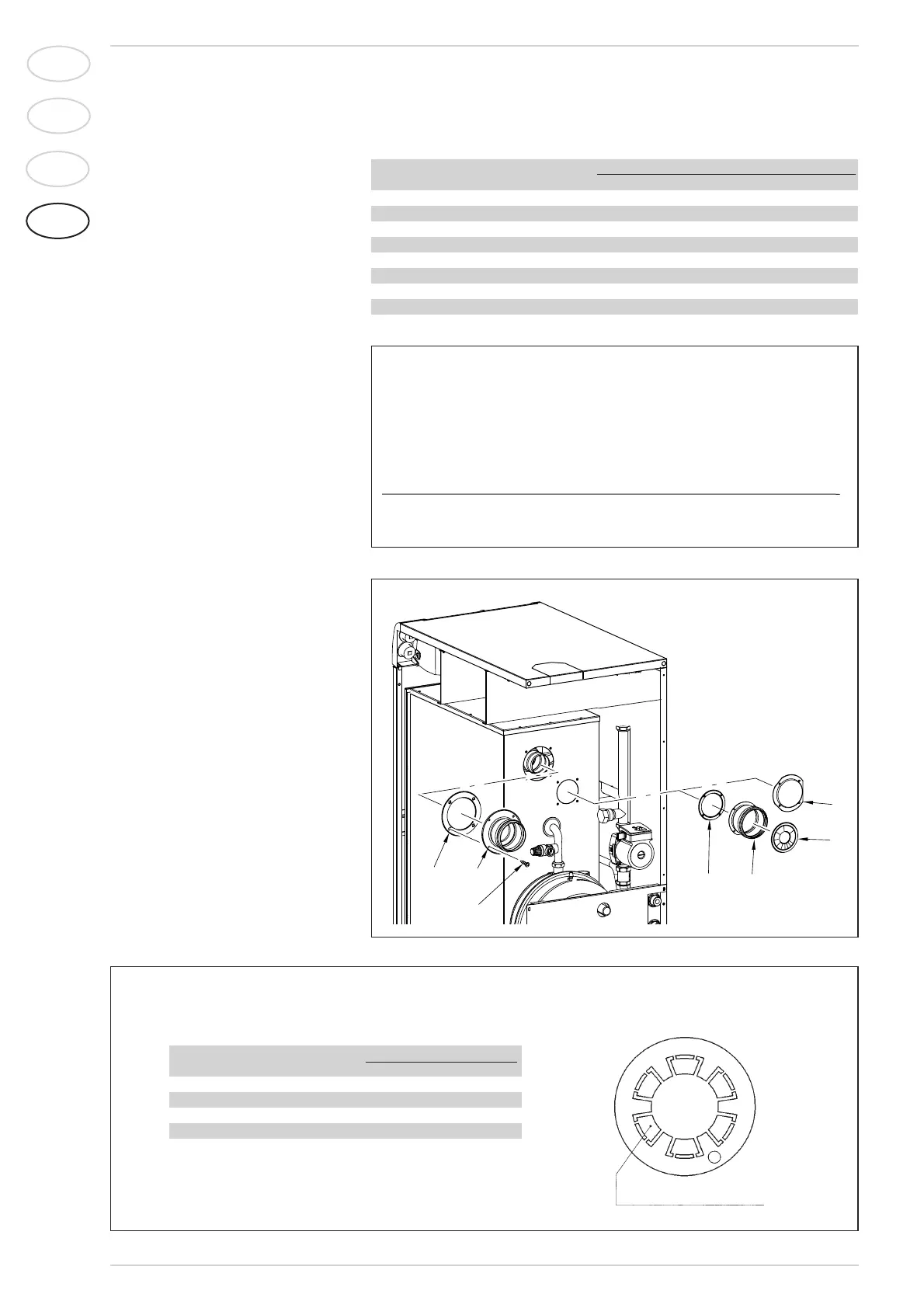
2.8.1 Separate flue kit (fig. 4)
The required intake diaphragm is supplied
with the separate duct kit code 8089905,
according to the maximum load allowed in
both ducts, as indicated in fig. 4/a.
2.8.2 Outlet systems
The diagrams in fig. 5 illustrate a number
of examples of different types of separate
outlets.
40
IT
ES
PT
GB
Fig. 4/a
Fig. 4
Example of allowable installation calculation in that the sum of the head losses of the
single fittings is less than 6,00 mm H
2
O:
Intake Outlet
6 meter horizontal pipe ø 80 x 0,20 1,20 –
6 meter horizontal pipe ø 80 x 0,40 – 2,40
n° 2 90° elbows ø 80 x 0,30 0,60 –
n° 2 90° elbows ø 80 x 0,50 – 1,00
n° 1 terminal ø 80 0,10 0,40
Total head loss 1,90 + 3,80 = 5,7 mm H
2
O
The intake diaphragm is to be removed with this maximum loss of load.
TABLE 1
Accessories ø 80 Load loss (mm H
2O)
Intake Outlet Roof out. Intake
90° elbow MF 0,30 0,50 –
45° elbow MF 0,20 0,40 –
Extension L. 1000 (horizontal) 0,20 0,40 –
Extension L. 1000 (vertical) 0,30 0,30 –
Outlet terminal – 0,40 –
Intake terminal 0,10 – –
Manifold 0,30 – –
Roof outlet terminal L. 1390 – – 0,60
Tee condensation outlet – 1,10 –
KEY
1 Blank flange
2 Outlet flange
3 Screw
4 Sponge sheath ø 125/95
5 Intake collar
6 Intake diaphragm
7 Sponge sheath ø 100/78
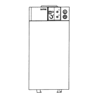
N° diaphragm sectors to remove Total load loss
mm H2OPa
1 0 ÷ 1 0 ÷ 9,8
3 1 ÷ 2 9,8 ÷ 19,6
4 2 ÷ 3 19,6 ÷ 29,4
6 3 ÷ 4 29,4 ÷ 39,2
Remove the diaphragm 4 ÷ 6 39,2 ÷ 58,8
DIAPHRAGM SECTOR