min. 700
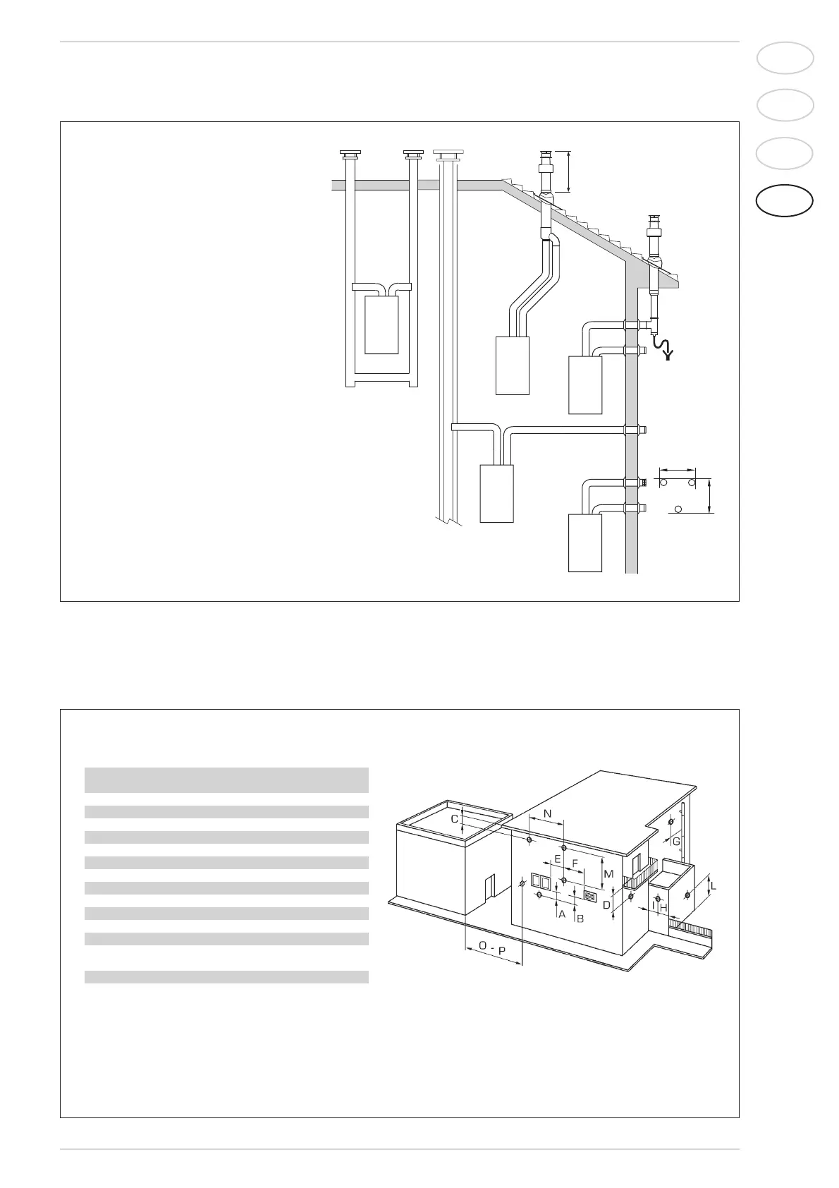
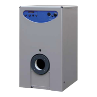
Fig. 5
LIST OF ACCESSORIES THAT ALLOW THE
CONFIGURATIONS INDICATED ARE SUPPLIED
ON REQUEST:
– Separate flue kit code 8089905
– 90° elbow MF code 8077410 (6 pz.)
– 90° insulated elbow MF code 8077408
– 90° elbow MF with take-off points
code 8077407
– Extension L. 1000 code 8077309 (6 pz.)
–
Insulated e
xtension L. 1000 code 8077306
– Extension L. 500 code 8077308 (6 pz.)
– Outlet terminal code 8089501
– Int.-est. ring kit code 8091500
– Inlet terminal code 8089500
– 45° elbow MF code 8077411 (6 pz.)
– Condensation outlet L. 135 code 8092800
– Doubler fitting code 8091400
– Tile with articulated joint code 8091300
– Roof outlet terminal L. 1390 code 8091201
– Tee condensation outlet code 8093300
WARNING:
- The outlet and intake ducts of type C52 cannot
be located on opposite walls.
- Types B22-B52 refer to the outlets of one
discharge duct only because suction is from
the environment.
TABLE 2
Siting of terminal Appliances from 7 to 35 kW
(distances in mm)
A - below openable window 600
B - below ventilation opening 600
C - below eaves 300
D - below balcony (1) 300
E - from adjacent window 400
F - from adjacent ventilation opening 600
G - from horizontal or vertical soil or drain pipes (2) 300
H - from corner of building 300
I - from recess in building 300
L - from ground level or other treadable surface 2500
M - between two terminals set vertically 1500
N - between two terminals set horizontally 1000
O - from a surface facing without
openings or terminals 2000
P - as above but with openings and terminals 3000
1)
Terminals below a practicable balcony must be located in such a way that the total path of the smoke from its outlet point from the terminal to its outlet
point from the external perimeter of the balcony, including the height of possible railings, is not less than 2000 mm.(?)
2) When siting terminals, where materials that may be subject to the action of the combustion products are present in the vicinity, e.g., eaves, gutters and
downspouts painted or made of plastic material, projecting timberwork, etc., distances of not less than 1500 mm must be adopted, unless adequate shiel-
ding is provided to guard these materials.
Fig. 6