2.10 ELECTRICAL
WIRING
If you must replace the electric power
cable supplied with the boiler, order it exclu-
sively from Sime.
The power supply must be single-phase
230V - 50 Hz through a main switch pro-
tected by a fuse with a distance of at least
3 mm between contacts.
Use only class II room thermostats in com-
pliance with the EN 60730 regulations
NOTE: Device must be connected to an
efficient eathing system. SIME cannot be
held liable for damage to people or things
that is due to non-earthing of the boiler.
Always turn off the power supply before
doing any work on the electrical panel.
42
IT
ES
PT
GB
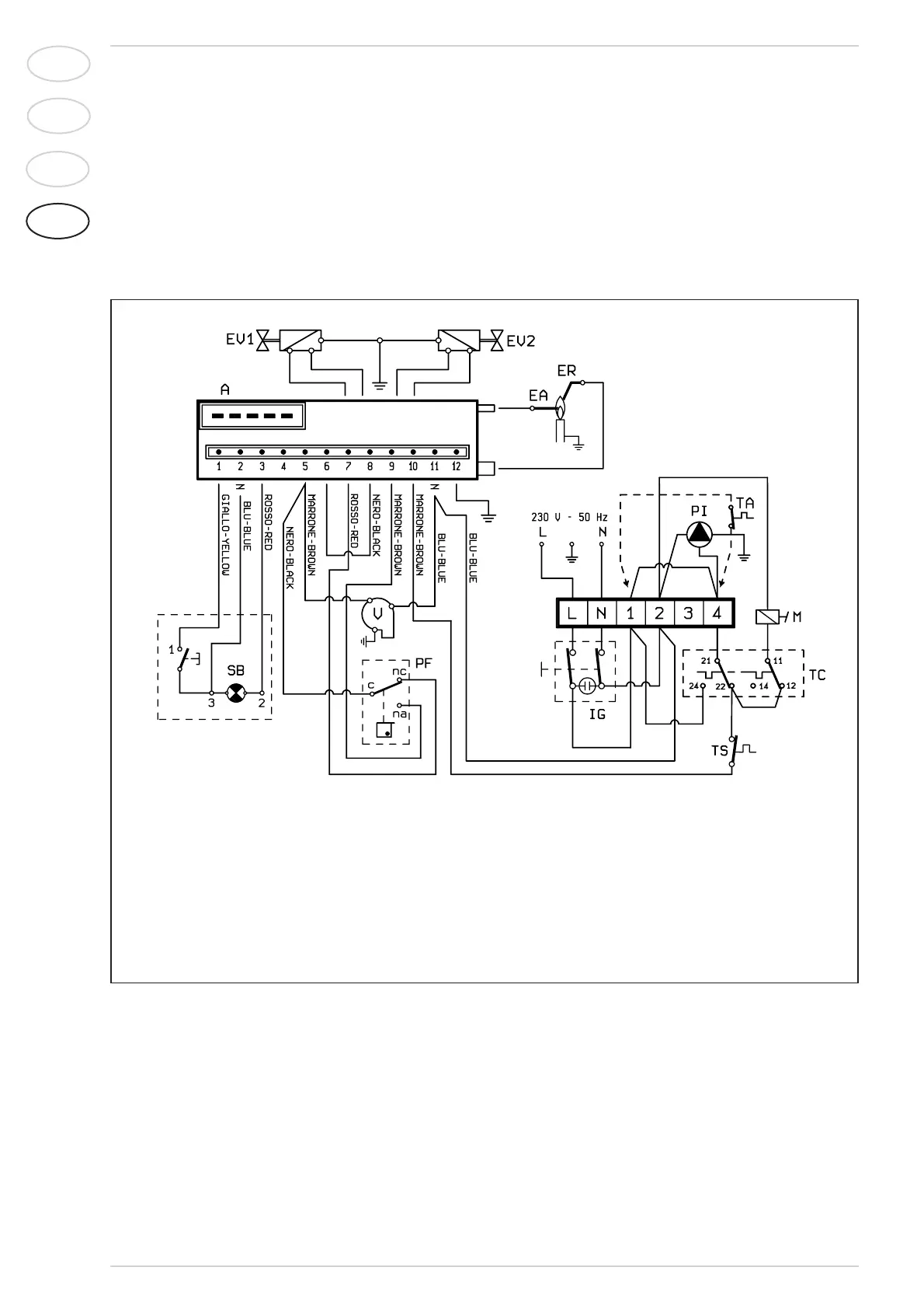
Fig. 7
2.10.1 Wiring diagram
KEY
A Control box
ER Detection electrode
EA Ignition electrode
EV1 Gas valve coil
EV2 Gas valve coil
VFan
PF Smoke pressure switch
TS Safety stat
SB Cotrol box lock-out
TC Boiler stat
M Modulator
IG Main switch
PI C.H. pump
TA Room stat
NOTE: Remove jumper 1-4 on the terminal board
while connecting the room thermostat (TA).