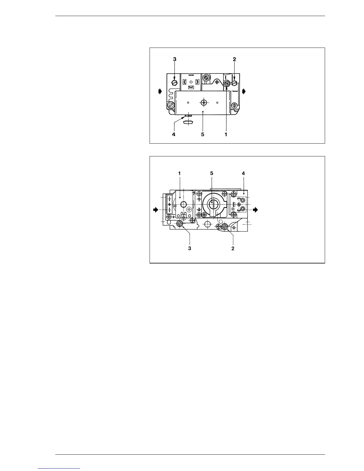
4.2 ADJUSTING GAS VALVE
“19-26 IONO” VERSIONS
Standard “RX 19-26 CE IONO” and
“RX 19-26 PVA CE IONO” boilers with
electronic ignition feature a SIT 830
TANDEM gas valve (fig. 9).
When the boiler is ignited for the first
time, it is always better to purge the
pipe through the pressure tap (3).
Remove the plug on the pressure regu-
lator (4) to adjust the main burner gas
pressure.
The regulation is made by rotating the
screw under the plug: rotate the screw
clockwise to increase the pressure,
anticlockwise to reduce it.
The valve can control a “soft” ignition of
the boiler through the screw (1).
Rotate the screw anticlockwise to
increase the burner “soft” ignition
pressure (STEP), clockwise to reduce
it. The optimum “soft” ignition values of
the burner depend on the type of gas:
– Methane 3 - 4 mbar
– Butane 6 - 7 mbar
– Propane 6 - 7 mbar
4.3 ADJUSTING GAS VALVE
“RX 37÷55 CE IONO” VERS.
The electronically ignited “RX 37+55
CE IONO” boilers are equipped with
the HONEYWELL VR4605C gas valve
(fig.10).
When igniting the boiler for the first
time, it is always advisable to purge the
pipe by opening the inlet pressure tap
(3). To adjust gas pressure to the main
burner remove the plug on the pressu-
re regulator (5).
Use a screwdriver to regulate the
screw under the plug: to increase pres-
sure screw clockwise, to reduce it
screw counterclockwise.
4.4 ADJUSTING THE GAS
PRESSURE TO BURNERS
Pressure calibration and gas input are
carried out by the manufacturer.
During installation of the equipment,
feed pressure might be different from
standard values.
It is therefore necessary to check
pressure and gas input when igniting
the boiler for the first time.
This test should be performed with the
boiler in full operation (obviously no
other gas appliances should be
working at the same time). Read the
gas meter twice every 6 minutes.
Multiply the consumption by ten to cal-
culate the consumption per hour.
If this value does not correspond to the
one in point 1.3, turn the screw of the
pressure regulator on the valve until
the exact value is obtained.
Screw slowly and gradually.
Read the gas meter at least thirty
seconds after regulating the pressure.
4.5 GAS CONVERSION
A kit is supplied complete with the
necessary change-over materials for
operation with butane gas (G30) or
propane gas (G31). Operate in the fol-
lowing manner for changing over from
one gas to another:
– Replace the main nozzles and pilot
nozzle supplied in a kit.
– Remove the plug on pressure regu-
lator and tighten the adjusting
screw (2 fig. 8 - 4 fig. 9 - 5 fig. 10).
–
Set valve input pressure at 30/37
mbar according to the type of gas by
acting on the outer pressure reducer.
–
When the working pressures have
been adjusted, reseal the regulators.
– After have ultimated the conversion
of the boiler, please stick onto the
casing panel the plate showing the
relevant feeding gas which is inclu-
ded into the kit.
NOTE: After assembling all the gas
connections, a test for gas tightness
must be carried out using soapy water
or special products. Do not use naked
flames. The conversion to different
gas must be carried out exclusively by
authorized technical personnel.
4.6 REMOVING THE CASING
It is possible to completely disassemble
the shell for an easy maintenance of
the boiler following these simple
instructions:
– Remove the boiler top which is fixed
with pressure plugs.
– Remove the panelboard.
– To remove the door, unscrew com-
pletely the screw fixing the top hinge
and lift the door, removing it from
the fixed plug of the bottom hinge.
52
KEY
1 “Soft” igniter regulator
2 Outlet pressure tap
3 Inlet pressure tap
4 Main burner
adjusting screw
5 EV1 - EV2 coil
Fig. 9
KEY
1 EV1 coil
2 Outlet pressure tap
3 Inlet pressure tap
4 EV2 coil
5 Pressure regulator
Fig. 10
 Loading...