3.1 ELECTRONIC IGNITION
The “IONO” boilers are equipped with
electronic ignition without pilot flame;
they are therefore equipped with an
electric control and protection device.
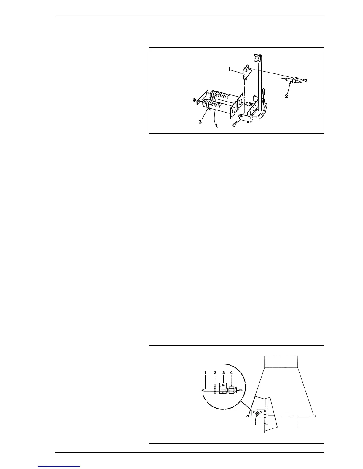
An electronic programmer, model
Brahma FM 11, controls the ignition
and the ionisation by means of two
electrodes as shown in fig. 5.
Maximum safety is garanteed because
in case of accidental extinction of the
burner the gas flow is stopped within 1
second. A reference mark made on
the burner ensures the proper applica-
tion of the ignition electrode.
3.1.1 Working cycle
Before lighting the boiler check with a
voltmeter that the electric connection
to the terminal board has been pro-
perly made observing the phase and
neutral positions of the wiring diagram.
Press the main switch on the control
board; the lamp will light if there is
power. At this stage the boiler will start
to work sending, via the FM 11 pro-
grammer, a discharge current to the
electrode and, at the same time, ope-
ning the gas valve. Normally the burner
takes 1 or 2 seconds to light.
It may however fail to light, in which
case the boiler lock-out lamp will be
activated. The main causes maybe:
– No gas supply
The equipment performs regularly
sending voltage to the ignition elec-
trode that continues to spark for max.
10 seconds, without detecting the
burner starting, then it shuts down.
It may occur at the first starting or
when the boiler has not been used
for a long period of time and there is
air in the pipes. It may occur if the
gas cock is closed or if the winding of
one of the valve coils is interrupted,
thus preventing it from opening.
– There is no spark
In the boiler you will only notice the
gas flow to the burner, after 10
seconds it shuts down.
It may be due to the fact that the elec-
trode cable is disconnected or is not
properly fixed to the terminal 10; or
the equipment transformer is burnt.
– No ionisation
From the time of the starting you
can observe the electrode continuos
sparking even if the burner is on.
After 10 seconds the sparking stops
and so does the burner, while the
lock-out lamp appears to be on.
It occurs if the phase and neutral posi-
tion on the terminal board has not
been observed. The detection electro-
de cable is disconnected or the elec-
trode itself is earthed; the electrode is
very worn-out and needs replacing.
The sudden lack of voltage causes the
immediate shutdown of the burner and
when the voltage is restored the boiler
will automatically restart.
3.1.2 Ionization circuit
The ionization circuit shall be checked
with a normal microammeter, or even
better, with a digital microammeter
with a 0÷50 µA range.
The microammeter terminals shall be
electrically connected in series to the
ionisation electrode cable.
Under standard conditions the value
varies from 4÷6 µA. The minimum ioni-
zation current value, at which the
equipment may shut down, is approxi-
mately 1 µA. In this case it will be
necessary to check that there is a
good electric contact and to check the
wear of the electrode tip and of its
ceramic protection.
3.2 SMOKE SAFETY DEVICE
The smoke stat provides a protection
against the discharge of flue gas into
the atmophere (3 fig. 2).This control
device stops the gas valve if the flue
gas is descharged into the boiler room
is continuous way and in such quanti-
ties as to become dangerous.
To start the boiler again, switch off the
power, then remove the smoke stat
cover and reset the button below.
If the thermostat continues to trip off,
it will be necessary to check the flue
thoroughly, making all the necessary
changes to ensure it works properly.
On the “RX 37÷55” models, the
smoke stat capillary on the back of the
boiler shall be put into the 12.5 ø hole
of the droughtdiverter support bracket
and fixed to it with the fitting and the
M12 lock nut already mounted on the
capillary (fig. 6).
50
3 CHARACTERISTICS
KEY
1 Ionisation electrode support
2 Ionisation electrode
3 Ignition electrode
Fig. 5
KEY
1 Smoke stat capillary
2 M12 lock out
3 Capillary support bracket
4 M12 fitting
Fig. 6
 Loading...