54
BOILER IGNITION
Follow these instructions to ignite the boi-
lers “RX CE” and “RX PVA CE” (fig. 11):
–
Press the gas valve (15) push button
hard and, simultaneously, push the
piezo igniter button (13) several times.
– Keep the valve button pressed for
15-20 seconds, then release it
checking that the pilot burner (11) is
on. Should it switch off, repeat the
operation.
– Switch the power on to make the boi-
ler operate.
On “RX IONO” and “RX PVA CE IONO”
models it is enough to switch on the
switch (1) to make the boiler operate
and begin heating.
ADJUSTMENT OF HEATING
TEMPERATURE
The heating temperature can be adju-
sted with the stat knob with a range
from 45ºC to 85ºC (16 fig. 11). The
temperature setting can be checked
on the thermometer (5 fig. 11). For an
always optimum operation of the boiler
we recommend not to reduce the ope-
rating temperature below 60ºC.
LOCK OUT RESET OF THE
CONTROL BOX
If, in the “IONO” models, the burner
does not ignite lock-out lamp will be
activated (2 fig. 11).
Press the resetting button to make
the boiler automatically start.
If, after trying to release the boiler
two or three times, this does not
regularly start, call on the authorized
technical personel.
SWITCHING OFF THE BOILER
To switch off the boilers “RX CE” and
“RX PVA CE” temporarily, it is enough
to turn the switch (1 fig. 11) to off, thus
clearing power to all electric devices;
only the pilot flame will keep burning.
To switch the boilers and their pilot
WARNINGS
– In case of fault and/or incorrect equipment operation, deactivate it, without making any repairs or taking any direct
action. Contact the nearest Authorised Technical Service Centre.
– The installation of the boiler and any servicing or maintenance job must be carried out by qualified personnel. Under
no circumstances, the devices sealed by the manufacturer can be tampered with (pr EN 89).
– It is absolutely prohibited to block the intake grilles and the aeration opening of the room where the equipment is
installed.
USER INSTRUCTIONS
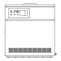
LIGHTING AND OPERATION
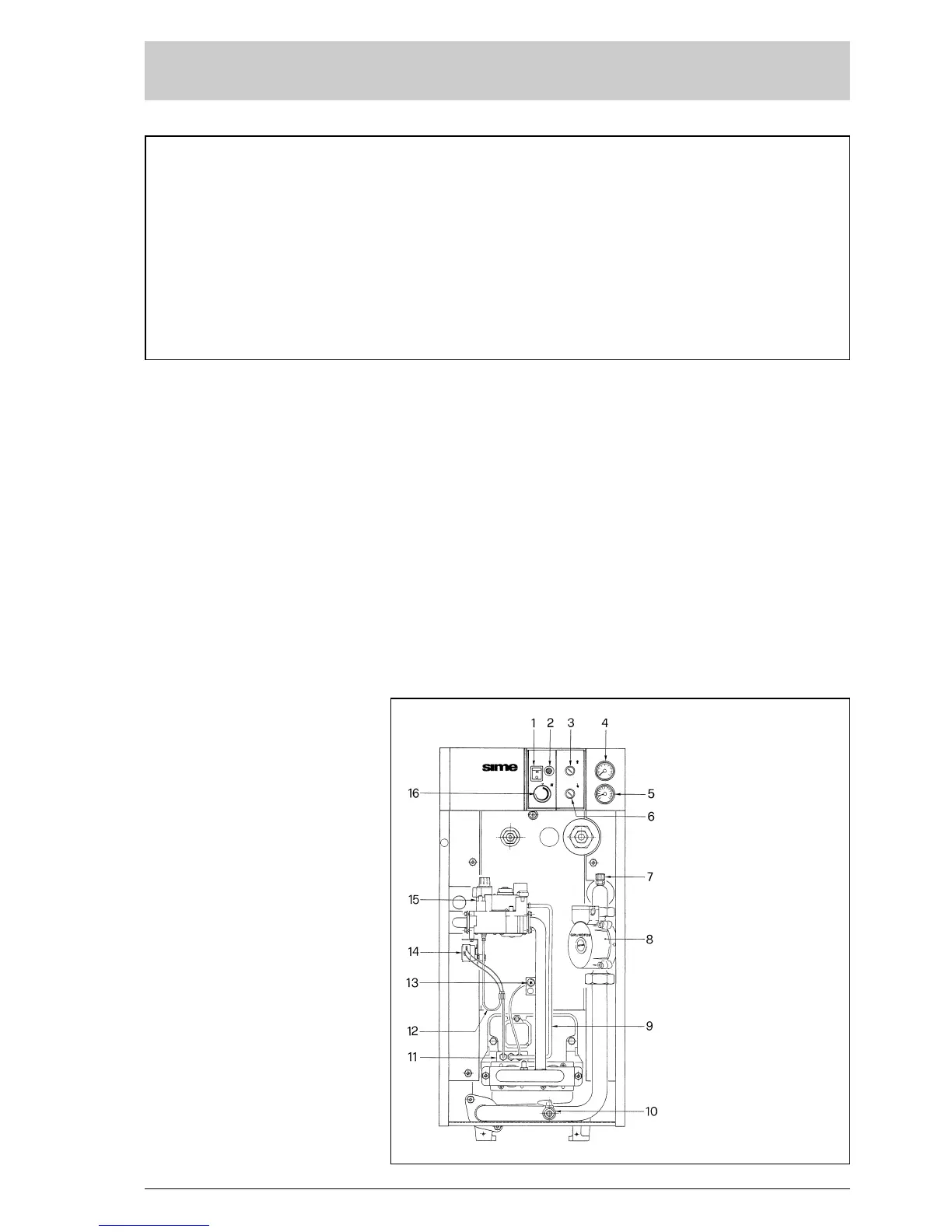
KEY
1 Main switch
2 Lock out lamp
(“IONO” vers.)
3 Smoke stat
4 Hydrometer
5 Thermometer
6 Safety stat (“IONO” vers.)
7 Air vent valve (“PVA” vers.)
8 Pump (“PVA” vers.)
9 Gas pilot tube
10 Drain cock (1/2”)
11 Pilot burner
12 Interrupted thermocouple
13 Piezoelectric ignition
14 Safety stat
15 Gas valve
16 Boiler stat
Fig. 11
 Loading...