49
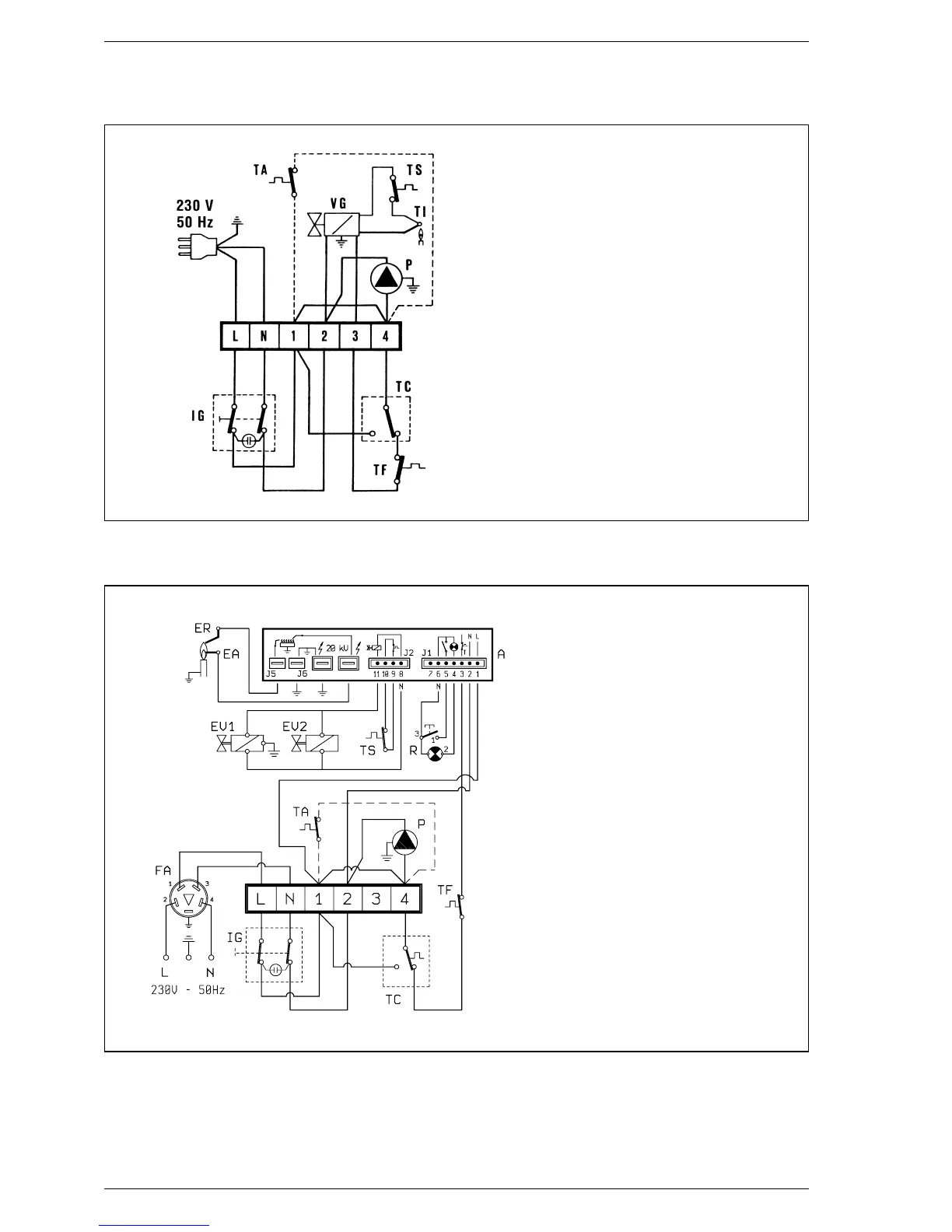
KEY
IG Main switch
P Circulating pump (“PVA” vers.)
VG Gas valve
TI Interrupted thermocouple
TC Boiler stat
TS Safety stat
TA Room stat
TF Smoke stat
Fig. 4
NOTE: Where the circulating pump is
installed outside the boiler the electric
connection must be made on the termi-
nals 2 and 4 of the terminal board,
otherwise the pilot flame may go out
KEY
A FM 11 programmer
IG Main switch
TC Boiler stat
EA Ignition electrode
ER Ionisation electrode
P Circulating pump
TS Safety stat
EV1 Modulating coil
EV2 Modulating coil
TF Smoke stat
R Lock out lamp
TA Room stat
FA EMC filter
NOTE: When a room stat is to be fitted
remove the link between terminal 1
and 4 on the connector plug.
2.6.1 “IONO” boiler wiring diagram
Fig. 4/a