DRAFT D
TNM-M-E-0001 Page
68
APPENDIX A - TRANSCEIVER CONNECTIONS
A.1. MICROPHONE / HANDSET CONNECTOR
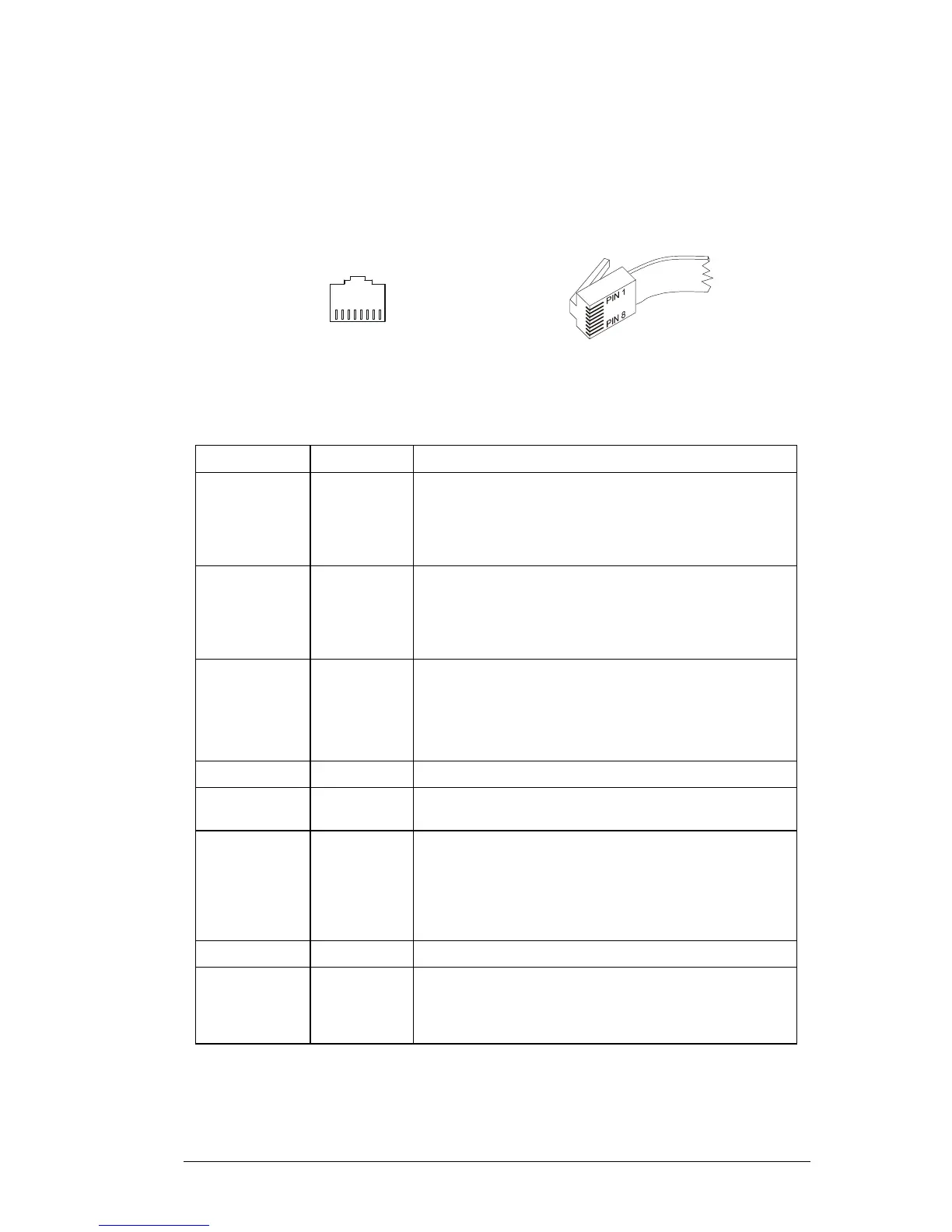
The Transceiver front end-cap has a 8 pin RJ45 Microphone / Control Unit / Serial Control /
Programming connector:
1
RJ45 Socket
(view looking into transciever)
RJ45 Plug
9k_00
8
Figure A.1 SRM9000 RJ45 Pinout (S1)
Name Pin Number Comment
Tx-Data (0,5V) 1 Output.
Low = 50mA sink to GROUND,
High = 6k8 Ohm pull-up to 5V
200 Ohm series Impedance
Diode Clamped to 0 & +5V
Rx-Data (0,5V) 2 Input.
Low < 0.5V, High > 2.5V
Internal 6k8 Ohm Pull-up to 3.3V
780 Ohm series Impedance
Diode Clamped to 0 & +3.3V
On/Off input 3 Input.
Low < 5V, High > (Supply Volts – 1.5V) or O/C
Internal 220kM Ohm Pull-up to Supply Voltage
680k Ohm series Impedance
Diode Clamped to 0 & Supply Voltage
Mic Ground 4 Connected internally to GROUND (see below)
+13.8V
(Switched OP)
5 Switched + Supply Voltage
250mA max source current
Handset Audio
OP (Flat)
6 Output: * Note-1
AC coupled (10uF) to 0/5V OpAmp Output
245mVrms (nominal) for 60% RF deviation of 1000Hz
tone.
600 Ohm series Impedance
Diode Clamped to 0 & Supply Voltage
GROUND 7 Internally connected to Transceiver –VE Supply Input.
Mic Audio IP 8 Input : * Note-2
40mVrms at 1kHz = 60% RF Deviation
>1k Ohm series Impedance
Diode Clamped to 0 & Supply Voltage