XFIN-BLADE-SM
DESCRIPTION PAGE 17
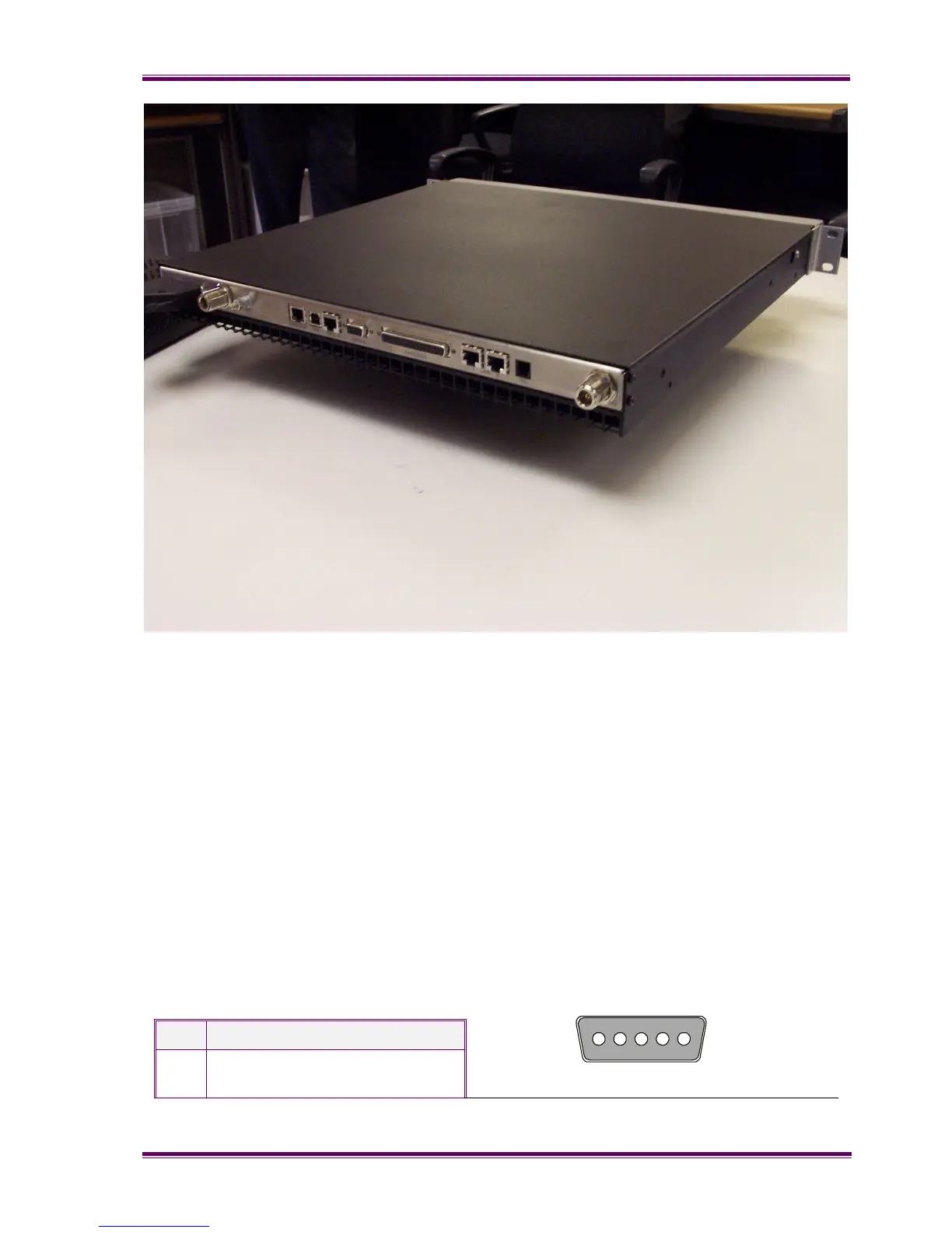
Figure 3.3 – View of the Xfin Blade rear panel.
3.5.1 Tx/Rx
The antenna connections on the Blade are provided with 50Ω female N-type sockets.
Mating connectors should be galvanically compatible with nickel outer and gold centre pin
to minimise passive inter-modulation.
A minimum of 85dB transmit-receive isolation should be provided by the antenna system
and associated filters.
It is recommended that a good quality flexible co-axial cable is used, e.g. with double-
screening braid and multi-strand copper inner.
3.5.2 Power
This is a D-type housing with 5 stud-pin locations. From left to right (looking at the rear
panel) they are:
Pin Description
1 Power amp (option). +24VDC
(nom)
1 5