PAGE 26 TECHNICAL DESCRIPTION
4.2.2 Circuit Description
See the Appendix for a more detailed block diagram representing the control card.
4.2.2.1 LEDs
LED DL1 indicates Ethernet connection (‘LINK’).
LED DL2 indicates the Flash device at U46 is being written to.
4.2.2.2 Test Points
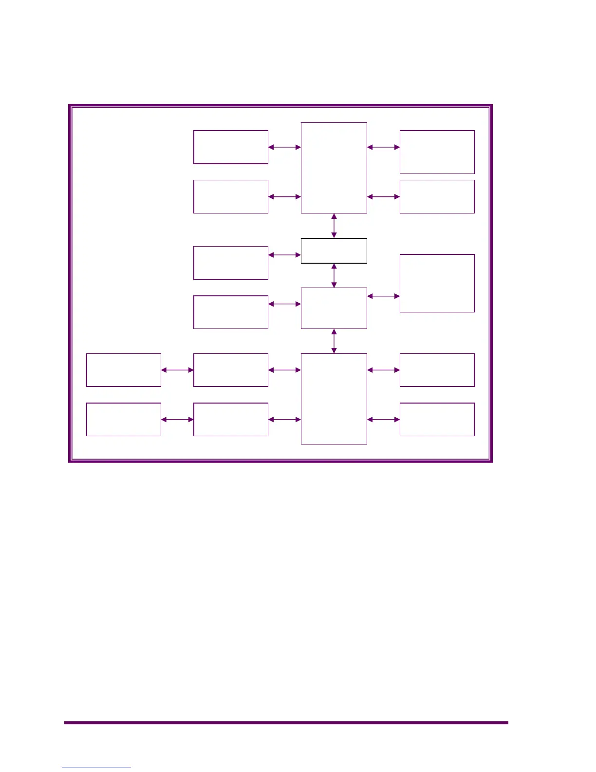
Figure 4.4 – Block Diagram of Control Board
IXP
DSP
CODECs
Analogue
I/O
Digital I/O
Ethernet
Control
Serial Port
Digital I/O
Serial
Control
Line Audio 1
Line Audio 2
Line
Barrier
Line
Barrier
BS Audio 1
BS Audio 2
SRM
Interface
CPLD