PAGE 20 DESCRIPTION
Where line barrier is not required, two fuses may be fitted in fuse-holders F3 and F4 of the
control PCB (20 x 5mm, 50mA) to provide DC ground and bias for E&M signalling.
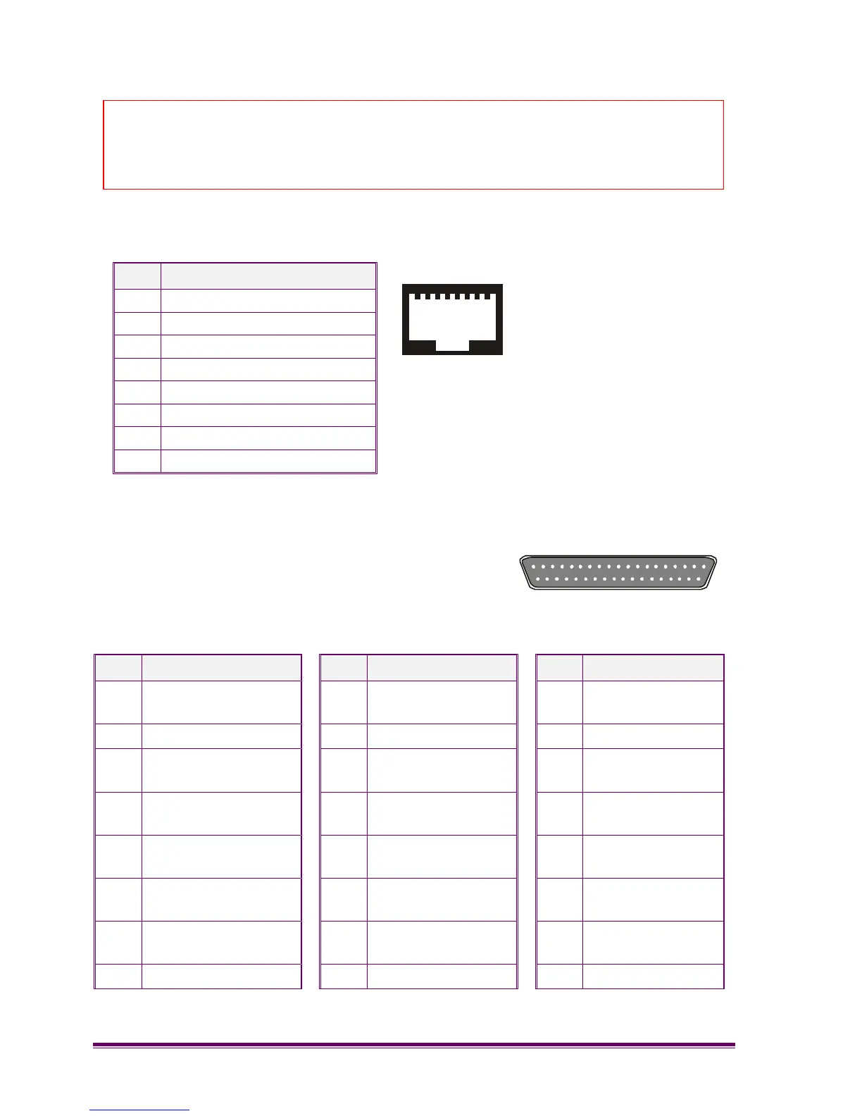
Pin Description
1 E+
2 M-
3 4 wire Tx
4 4 wire Rx or 2 wire Tx/Rx
5 4 wire Rx or 2 wire Tx/Rx
6 4 wire Tx
7 M+
8 E-
3.5.9 Facilities
This 37-way D-type can be programmed for any
combination of digital inputs and outputs. Audio signals
are present on certain pins, these require an adapter
cable in order to re-route signals and become plug
compatible with certain products.
Pin Description Pin Description Pin Description
1 Tx+ line connection
A
14 CTCSS decode
defeat
27 I/O 5
2 0v 15 RSSI O/P 28 I/O 6
3 Rx+ line connection
A
16 Channel line C6
(MSB)
29 Talkthrough
command
4 Rx+ line connection
B
17 Channel line C4 30 Squelch defeat
command
5 Tx+ line connection
B
18 Channel line C2 31 I/O 7
6 Tx- line connection
B
19 Channel line C0
(LSB)
32 Aux Rx
7 I/O 2 20 Tx- line connection
A
33 I/O 8
8 I/O 4
21 Aux Tx
34 Analogue Out
Caution
When the following is performed, the line barrier is breached and the
equipment must NOT be connected to Public Networks.
1
8
1
20
19
37