Assembly instructions for kit #9
All rights reserved. 2013 Simple Motors, LLC ♦ www.simplemotor.com ♦
6
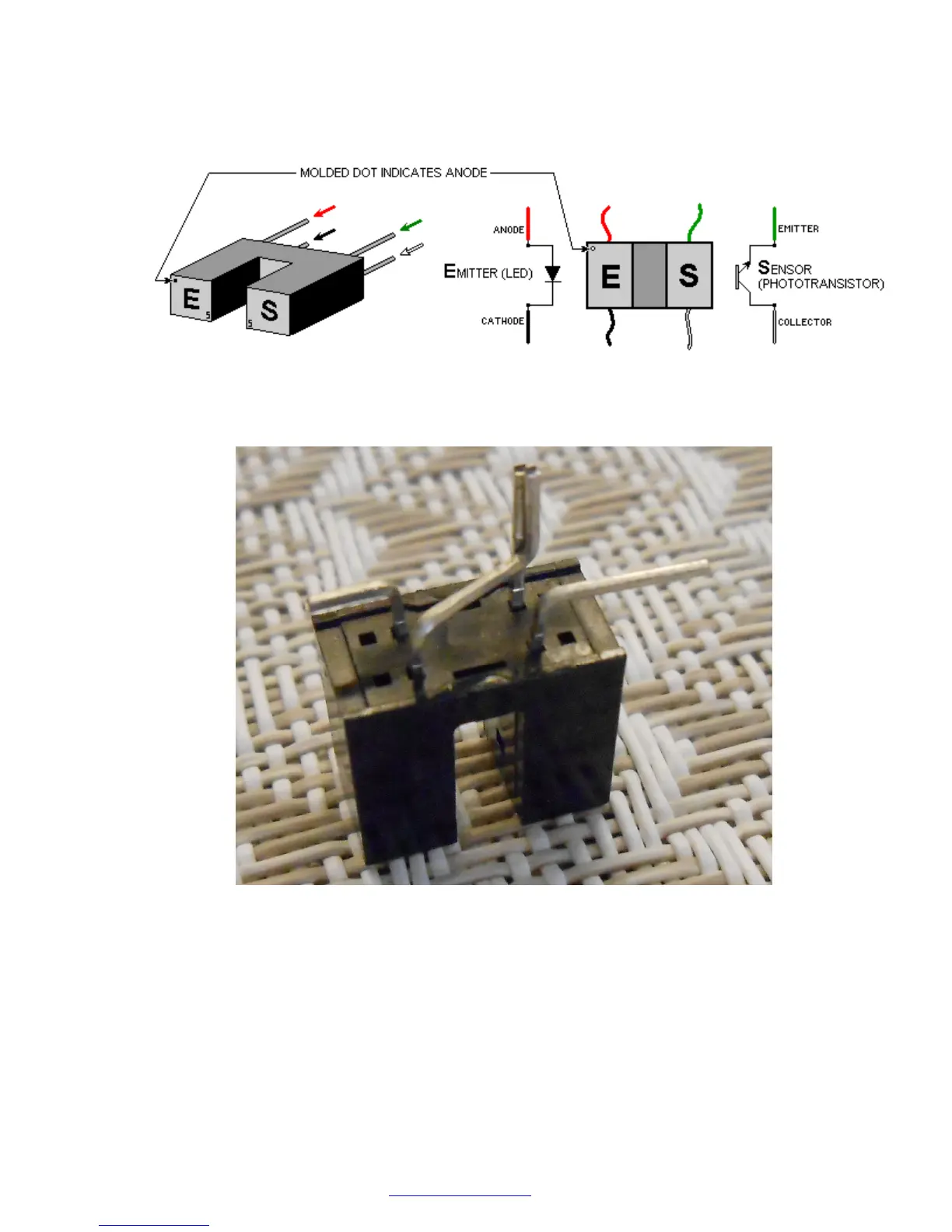
14.Locate the optointerrupter pins as shown on the following picture. It is very important to
identify all four pins properly. Wrong connection in the motor will destroy the
optointerrupter.
Bend and trim optointerrupter pins as shown below (view from non-branded side). Tweezers
or needle-nose pliers may be very helpful. You may use scissors for trimming.
Locate the 270 Ohm and 4.7 K (4700 Ohm) resistors. The 270 Ohm resistor has red, violet,
brown and gold color bands. The 4.7 K resistor has yellow, violet, red and gold color bands.
Bend the leads of the resistors as shown below.
Solder these resistors together and to the optointerrupter as shown in the next picture. See
the Links page at our web site for tips on soldering if you do not have enough experience in
this procedure.
IMPORTANT: Do not overheat the optointerrupter when you solder it. The soldering iron
heat may destroy this sensitive device. If you were unable to attach the wire in 3 seconds,
let the optointerrupter cool off, and then try it again.