Assembly instructions for kit #9
All rights reserved. 2013 Simple Motors, LLC ♦ www.simplemotor.com ♦
7
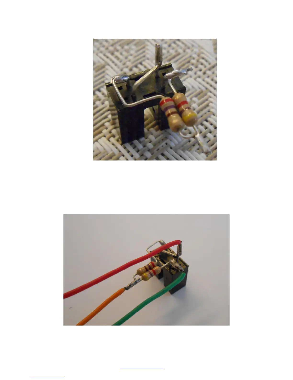
Make sure that 270 Ohm resistor is connected to LED cathode, 4.7 K resistor is connected to
the emitter of the phototransistor, and LED anode and the collector of the phototransistor
are connected together:
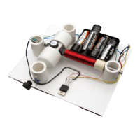
15.Solder 3 pieces of the hook-up wire to the optointerrupter assembly. If your kit includes one
large piece of hook-up wire, cut it into 8 pieces of about 9” (22-23 cm) each; if it includes
four 18” long pieces cut them in half. Strip about 3/8" (10 mm) of insulation on each end of
these wire pieces using a sharp knife.
Wire colors shown on the picture are used for reference only. You may use different colors
or even one color.