Assembly instructions for kit #9
All rights reserved. 2013 Simple Motors, LLC ♦ www.simplemotor.com ♦
9
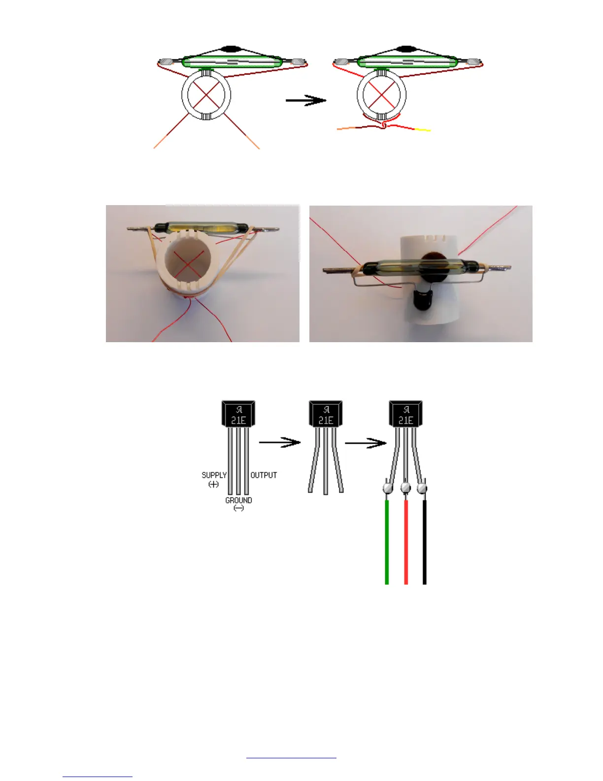
Use rubber band to prevent the reed switch from moving. The ZNR should be located below
the reed switch.
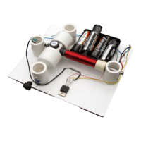
19.Bend the leads of the Hall Effect switch apart and solder three wire pieces to them. Do not
overheat the Hall Effect switch.
20.Insert the Hall Effect switch into the universal stand as shown below. Note that reed switch
and Hall Effect switch will be controlled by different magnets to reduce the interference.
Make sure that the leads of the Hall Effect IC do not touch each other and branded side is
facing down.