6.3 Auxiliary relays
The control unit has three onboard relays . The contact rating for auxiliary relays is 24 VDC at 2 A. You can select each relay for normally
closed or normally open operation. For the relay settings, see Table 6.
• Relay 1 is the common trouble relay and is normally energized. Relay 1 is non programmable.
• When the control unit is completely powered off, the default setting of the trouble relay is Off Normal.
Relays 2 and 3 are programmable. The default operation for relays 2 and 3 are as follows:
• Relay 2 is the common alarm and the default setting for Relay 2 is On Until Rest.
• The default setting for relay 3 is common supervisory.
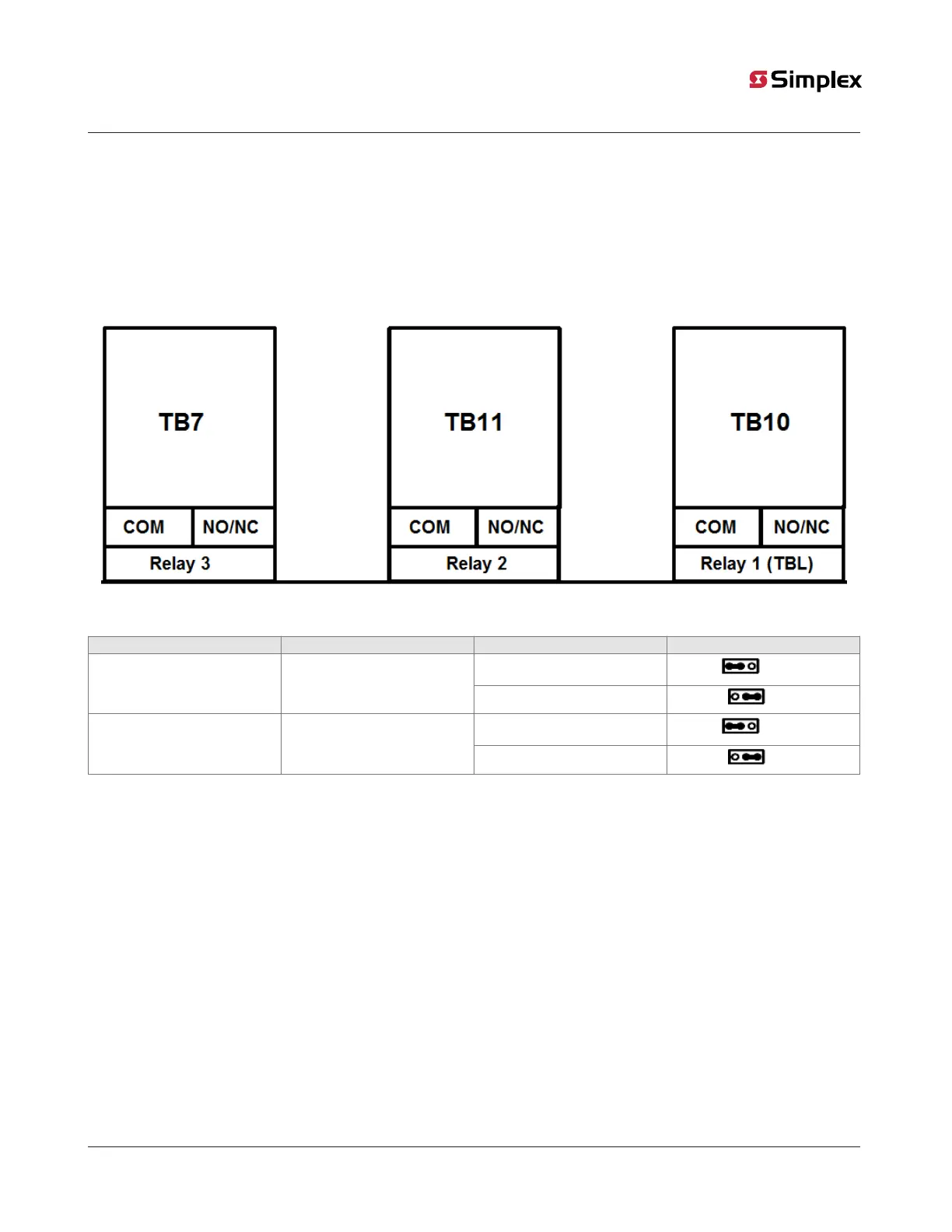
Figure 12: AUX relays
Table 6: Relay settings
Ref designator Functions Settings Jumper position
Normally open
1-2 (Left)
P21 Relay 1 contact setting
Normally closed (Default)
2-3 (Right)
Normally open (Default)
1-2 (Left)
P20 and P19 Relays 2 and 3 contact setting
Normally closed
2-3 (Right)
6.3.1 Wiring auxiliary relays
To wire an auxiliary relay, check that the following reqiurements are met:
• All wiring is between 18 AWG minimum and 12 AWG maximum.
• Check that the conductors test free of all grounds and stray voltages before you connect the auxiliary relay to the control unit.
• All wiring is unsupervised.
Note: All auxiliary relay loads must be powered from the AUX power circuit or from a regulated, 24 VDC, power limited power supply that is
UL-listed for fire protective signaling service.
page 23 579-1404 Rev A
2050 and 2250 Foundation Series Fire Alarm Control Units Installation Guide