9 Fuse replacement procedure
To replace the fuse, follow these steps:
1. Remove the AC power to the control unit.
2. Open the panel door and remove the insulating cover of the FACU. The insulating cover has a high voltage warning on the front.
3. The fuse is installed on the power supply board that is mounted inside the chassis in front. Remove the chassis with the control
unit board and power supply assembly. See Mounting the back box for assembly connections to the chassis.
4. Remove the J3 connector on the control unit board and remove first the control unit board from chassis.
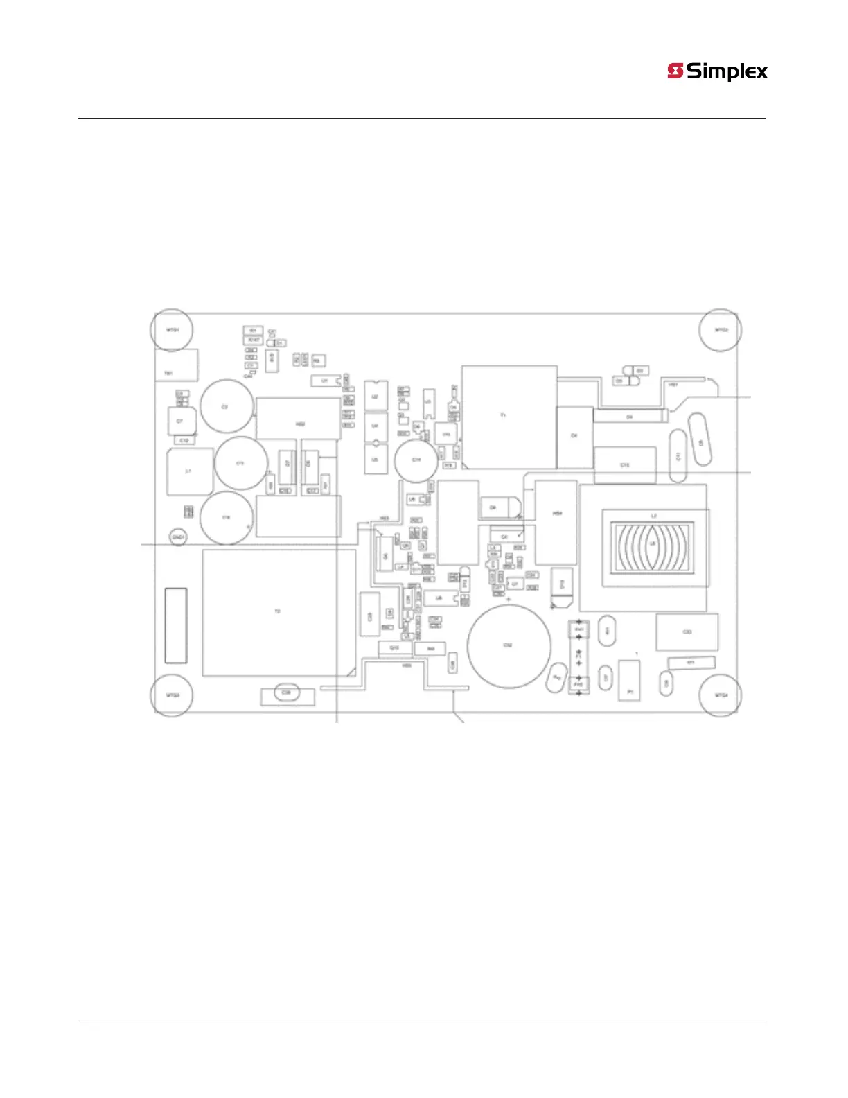
5. Remove the SMPS board from the chassis and identify fuse F1 on this board.
6. Remove the fuse from the fuse holder and verify if the fuse is ruptured.
Figure 22: PCB component silkscreen
7. If the fuse is faulty, replace it with an intact fuse that has the following ratings:
- Voltage: 250VAC
- Current: 5 A
- Size: 5mm x 20mm
- Glass tube
8. Reconnect the power supply and the control unit board to the chassis.
9. Mount the chassis assembly back into the panel enclosure as in Mounting the back box.
10. Reattach the insulating cover and connect to mains power.
Note: Only a qualified service technician can replace the fuse with specified rating 250 VAC, 5 A.
page 34 579-1404 Rev A
2050 and 2250 Foundation Series Fire Alarm Control Units Installation Guide