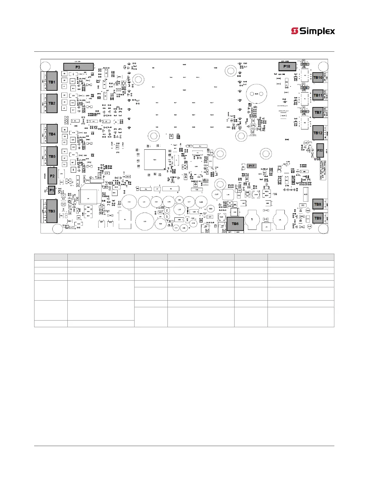
Figure 1: 2250 control unit board
Table 1: Main components information
Identifier Description Identifier Description Identifier Description
TB1 NAC1 TB7 Relay-3 P3 LCD display connector
TB2 NAC2 TB8 Aux-1 (Non-resettable power) P17 RFID connector
TB3 MX Loop TB9 Aux-2 (Resettable power) P18 City Card connector
TB10 Relay-1 P19 Jumper for Relay-3 settingTB4 NAC3
The TB4 is not available in the
2050 control unit board
TB11 Relay-2 P20 Jumper for Relay-2 setting
P1 Gateway module connector P21 Jumper for Relay-1 settingTB5 NAC4
The TB5 is not available in the
2050 control unit board
TB6 Battery terminal
P2 Gateway module power
connector
P22 USB port
page 5 579-1404 Rev A
2050 and 2250 Foundation Series Fire Alarm Control Units Installation Guide