3
The city connect card has jumper settings that select either the Remote Station
(Reverse Polarity) Interface (see Table 1), which is the default jumper setting
from the factory, or the Municipal Master (Local Energy) Interface. Jumper
settings to configure the city connect card for the Remote Station Interface or
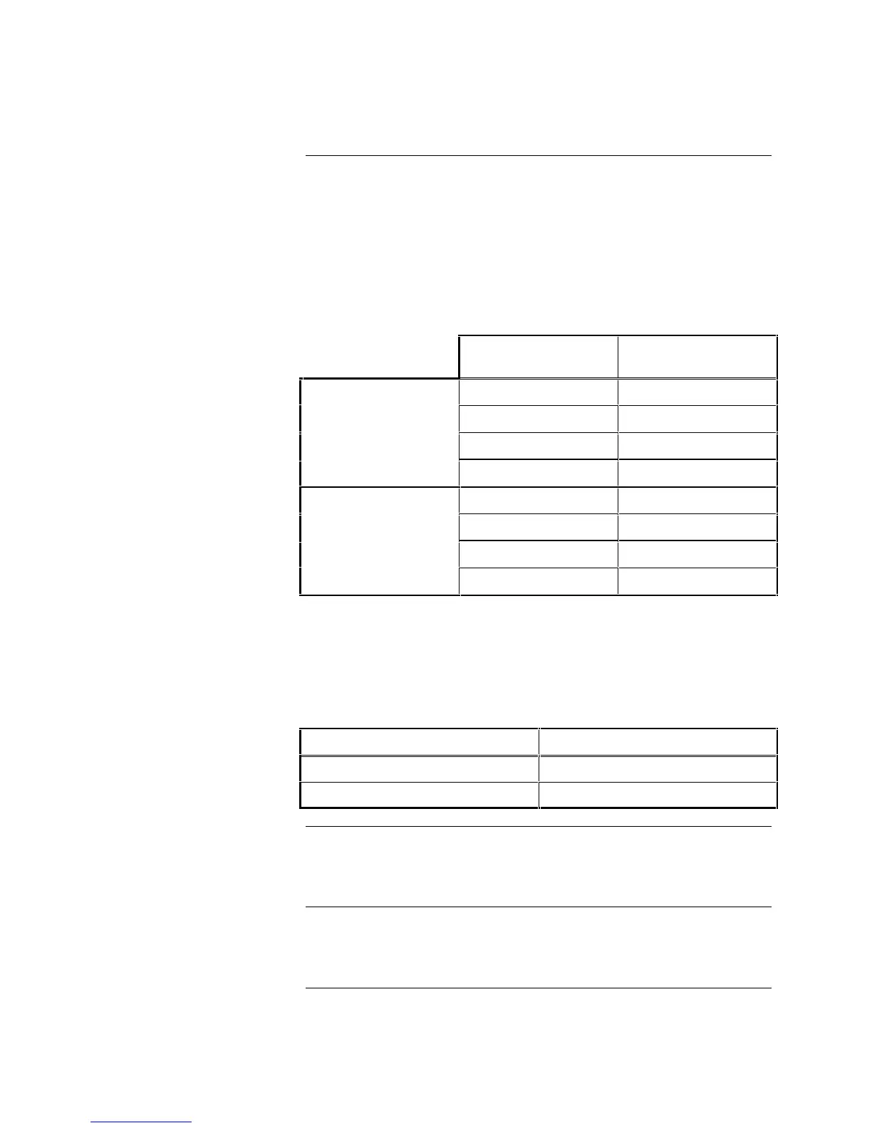
the Municipal Master Interface are listed below. The city connect card has
silk-screening that illustrates the jumpers and selectable configurations
(“RP” = Reverse Polarity, “LE” = Local Energy).
Table 1. Jumper Settings
Municipal Master
(Local Energy)
Remote Station
(Reverse Polarity)
P2-1 to P2-2 P2-2 to P2-3
P3-7 to P3-8 P3-1 to P3-2
P3-9 to P3-10 P3-3 to P3-4
City Circuit 1
—— P3-5 to P3-6
P4-1 to P4-2 P4-2 to P4-3
P5-7 to P5-8 P5-1 to P5-2
P5-9 to P5-10 P5-3 to P5-4
City Circuit 2
—— P5-5 to P5-6
Note: City Circuit 2 can also be selected for Remote Station Supervisory or
Trouble Operation (See Table 2) by setting the following jumpers.
When City Circuit 2 is selected for Trouble Operation, City Circuit 1
reports Alarm only.
Table 2. Operation of City Circuit 2
Supervisory Operation Trouble Operation
P6-1 to P6-2 ——
P6-3 to P6-4 P6-2 to P6-3
The City Connect Card (565-577 and 565-999 only) has two disconnect service
switches (SW1 and SW2); the normal position for both switches is the active
“ON” position. City Connect Card (566-078) does not have these switches.
Power-up the 4004 System and configure the city connect card using the
programming instructions located on the Termination Wiring Label
(519-698) inside the door.
City Connect Card Installation, Continued
Jumper Settings
Switch Settings
Power-up and Configuration
Technical Manuals Online! - http://www.tech-man.com