2
For all wiring information, use the 4004 Field Wiring Diagram (841-992). Also
reference the Contractor Wiring Termination Label (519-698) inside the 4004
Door Panel. The label shows the following information:
• The installation location of the city connect card.
• The location of the wiring harness.
• Harness interconnection with the system card.
• The location of the city disconnect switches.
• Programming information necessary to configure the card.
To mount the city connect card, follow Steps 1 through 3 while referring to
Figure 1.
CAUTION: Disconnect 4004 Panel power at the breaker before
installing the city connect card.
1. Remove the city connect card from the packing material.
2. Install the city connect card by securing it with four #6 Torx screws
(supplied).
3. Connect the Cable Harness (733-875) from the City Connect Card (P1) to
the System Board (P5).
P3
P2
LERP
LERP
P5
P4
LERP
LERP
TB1
1
4
CITY1+ CITY1- CITY2+ CITY2-
P6
11
332 1 2 1
O
N
O
N
1
2
3
4
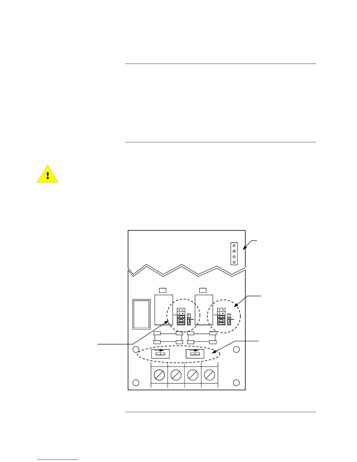
Figure 1. City Connect Card
Continued on next page
City Connect Card Installation
Introduction
Mounting
Supervisory or
trouble operation
jumper plug (P6)
City Circuit 2
jumper plugs
(P4 and P5)
City Circuit 1
jumper plugs
(P2 and P3)
Disconnect Switches
(SW1 and SW2)
located on 565-577 and
565-999 only. The
switches are not present
on 566-078.
P1
Technical Manuals Online! - http://www.tech-man.com