Do you have a question about the Simplex 4005 and is the answer not in the manual?
Overview of the publication and its purpose for the Simplex 4005 Fire Alarm system.
Lists of related publications for the Simplex 4005 Fire Alarm system.
Topics covered in Chapter 1, including system overview, product details, and modules.
Tables detailing product and part numbers for base panel and optional modules.
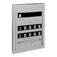
Overview of the 4005 system, its layout, features, and components.
Lists the various features of the 4005 fire alarm system.
Details the electrical input power requirements for the 4005 system.
Specifies battery backup capacity and grounding precautions.
Lists components of the 4005 base panel and references installation instructions.
Describes the functions and components of the 4005 CPU board.
Details the 4005's power supply, charging functions, and monitoring.
Explains the Power Distribution Board's function for I/O cards and power.
Describes the 4-Point IDC card for monitoring zones.
Explains the 4-Point NAC/Relay card's output points and configuration.
Introduces optional modules and references their installation.
Details the card combining IDCs and configurable outputs.
Explains the card for converting IDC/NAC points to Class A.
Describes the card providing eight configurable input/output points.
Details the optional power supply adding external power.
Explains the card for city connection, configurable for modes.
Describes the card for alarm communication to a remote station.
Describes the chapter's content on installing, wiring, and checking out the 4005.
Topics covered in Chapter 2.
Advises on notifying personnel and understanding instructions before installation.
Lists necessary tools and equipment for installing the 4005 system.
Provides instructions and diagrams for installing the back box.
Introduces the operator interface, control keys, LEDs, and LCD.
Topics covered in Chapter 3.
Details the components of the 4005 control panel, including LCD, LEDs, and keys.
Describes the step-by-step process of powering up and initializing the 4005 system.
Explains system behavior under normal and abnormal conditions.
Defines the functions of the operator keys (ACK, Silence, Reset).
Defines menu navigation keys and rules for system interaction.
Describes how the system indicates abnormal conditions via LEDs and tone-alerts.
Explains how to acknowledge and review abnormal conditions using ACK keys.
Details procedures for silencing alarms and resetting the system.
Explains how to perform a warm start to return the system to normal.
Discusses passcode protection, access levels, and menu structure.
Provides instructions for logging into and out of the 4005 system.
Describes the three log types (Alarm, Trouble, Combined) and stored events.
Explains how to view, clear, and interpret log messages.
Explains how to perform a Walk Test for the 4005 system, including options.
Describes how to navigate and view specific points within the system.
Provides steps for editing custom labels for points on the 4005.
Explains how to disable or enable active points on the 4005 system.
Lists common control functions available in the Function Menu.
Describes how to activate the Manual Evacuation operation.
Explains City Circuit Disconnect, Control Point Bypass, and Elevator Bypass.
Details procedures for Doorholder Bypass and Lamp Test functions.
Defines key terms used in the 4005 Fire Alarm system manual.
Lists regulatory information, including NFPA standards and UL listings.
Lists relevant codes and standards for installing the fire alarm system.
Refers to a replica instruction sheet for ready reference next to the control panel.
Simplified steps for responding to an alarm, acknowledging, and silencing.
Simplified steps for responding to trouble/supervisory conditions, acknowledging, and resetting.
| Brand | Simplex |
|---|---|
| Power Supply | 24 VDC |
| Operating Temperature | 32°F to 120°F (0°C to 49°C) |
| Humidity Range | Up to 93% RH, non-condensing |
| Compatibility | Compatible with Simplex fire alarm control panels |


