1-6
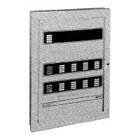
The 4005 base panel consists of:
• Fire Alarm CPU Board
• 4 Amp Power Supply/Charger.
• Two 4-point IDC Cards (low-current) with 8 points configured as Point
Type FIRE
• One 4-point NAC/Relay Card with 4 points configured as NACs, Point
Type SSIGNAL.
• A capacity to hold up to ten I/O cards (10 Slots).
The base 4005 panel comes completely assembled and ready to install in the
back box. Refer to Figure 1-1 (page1-3) and the Module and Wiring
Identification Chart on the inside of the panel door for the locations of each card.
Refer to Table 1-1 (page 1-2) for Product (PID) and Part numbers.
For more information on the following modules, refer to each of their individual
installation instructions:
• I/O Cards (Publication No. 574-070)
• City Circuit Card (Publication No. 574-071)
• Power Distribution Card (Publication No. 574-072)
The 4005 CPU board controls the system’s functions. The CPU is responsible
for all alarm and supervisory actions as well as the control of the front panel
display which provides the operator interface.
The 4005 CPU board contains:
• Main microprocessor and system memory
• Tone alert
• LCD
• Control panel with operator key inputs
• LED indicators
• Internal system connectors
• Field wiring terminal block for RUI and 4-wire detector power connectors
Continued on next page
Base Panel Modules
Overview
CPU Board
Technical Manuals Online! - http://www.tech-man.com
 Loading...


