3-1
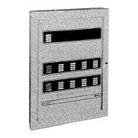
The operator interface with the system consists of control keys, LEDs, a 2-line
by 40-character backlit LCD (see Figure 3-1 for the positions of each), and a
tone-alert which are mounted in the control panel. The purposes of the controls
and indicators are listed in the Operation section of this chapter (page 3-4).
This chapter discusses the following topics:
Topic See Page #
Overview 3-1
System Initialization 3-3
Operation 3-4
Handling Abnormal Conditions 3-8
Passcodes and Access levels 3-11
Logs 3-13
Walk Test 3-16
Control / View Points 3-17
Function Menu 3-21
Location of Tables and Diagrams in this chapter:
Tables and Diagrams See Page #
Figure 3-1. Operator Interface (Control Panel) 3-2
Figure 3-2. Trouble Display 3-3
Figure 3-3. Abnormal Condition Display 3-8
Figure 3-4. Menu Structure (Access level 1) 3-11
Figure 3-5. Viewing History Log 3-13
Figure 3-6. Clearing a Log 3-14
Figure 3-7. Log Display format 3-14
Figure 3-8. Log Display 3-14
Figure 3-9. Secondary Log Display Format 3-15
Figure 3-10. Secondary Log Display 3-15
Figure 3-11. Walk Test Intital Display 3-16
Figure 3-12. Walk Test Option Displays 3-16
Table 3-1. System Initialization Functions 3-3
Table 3-2. Login Levels (Access Levels) 3-11
Table 3-3. Editing a Point Custom label 3-18
Table 3-4. Custom Point Label Characters 3-19
Table 3-5. Viewing and Disabling/Enabling a Point 3-20
Table 3-6. Function Menu Options 3-21
Table 3-7. Manual Evacuation 3-21
Table 3-8. City Circuit Disconnect 3-22
Table 3-9. Control Point Bypass 3-22
Table 3-10. Elevator Bypass 3-23
Table 3-11. Doorholder Bypass 3-23
Table 3-12. Lamp Test 3-24
Chapter 3
System Operation
Overview
In this Chapter
Technical Manuals Online! - http://www.tech-man.com
 Loading...


