6
The relay modules can be mounted to either 4100 Back Boxes (PID series 2975-91xx) or
4100U/4100ES Back Boxes (PID series 2975-94xx) as follows:
• The 4120-3001, -3002, and -3003 are used for systems with 4100 Back Boxes.
• The 4100-3201 through -3204 and -3206 are used for systems with 4100U/4100ES
Back Boxes.
This section describes mounting the 4120-3001 through -3003 into 4100 Back Boxes.
For instructions on mounting the 4010-9908 into a 4010ES back box, see “Installing Boards
into 4010ES Back Boxes” in this document.
Use the following guidelines and instruction when installing into a master controller bay.
• If the 575-274 Master Motherboard is used, it must be installed in the leftmost position of
this bay. If the 575-274 Master Motherboard is not used, the master controller
motherboard must be installed in the leftmost position of the bay.
• The power supply must be installed in the rightmost position of the bay.
• Relay cards must be installed in the slots immediately to the left of the power supply.
This is necessary to allow for the proper routing of non-power limited wiring (120 VAC
wiring connected to the relay card).
• If used, the Class B motherboard (575-275) must be installed to the left of the relay cards.
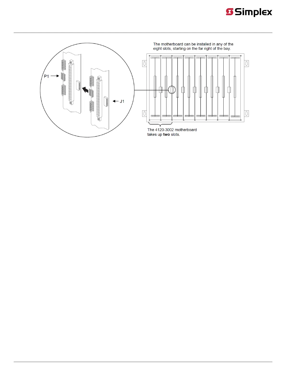
Install the motherboard as described below.
1. Orient the motherboard so that the connector labeled J1 is on the right and the header
labeled P1 is on the left.
2. Slide the motherboard you are installing to the left until the pins are completely inserted
in the connector of a previously installed motherboard.
3. Secure the motherboard to the chassis with four torx screws.
Figure 2. Installing the Motherboard into a 4100 Master Controller Bay
Installing Motherboards into 2975-91xx Back Boxes (4100)
Overview
Installing into a
2975-91xx Master
Controller Bay
Master controller
or 575-274
Motherboard
Power
Supply
J1
P1
Relay motherboards must be
placed in the rightmost slots.
The 4120-3002 motherboard
takes up two slots.